 |
||
|
|
||
| |||||||||||||||
|
|
WELDED STEEL TRUSSES Figure 7-6 is a drawing of a typical welded steel truss. When you interpret the welding symbols, you will see that most of them show that the structural angles will be fillet welded. The fillet will have a 1/4-inch radius (thickness) on both sides and will run along the angle for 4 inches. RIVETED STEEL STRUCTURES Steel structural members are riveted in the shop where they are fabricated to the extent allowed by shipping conditions. During fabrication, all rivet holes are punched or drilled whether the rivets are to be driven in the field or in the shop.
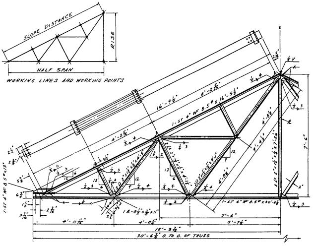
Figure 7-6.-Welded steel truss. Go to figure 7-7 and look at the shop fabrication drawing of a riveted steel roof truss. At first look, it appears cluttered and hard to read. This is caused by the many dimensions and other pertinent facts required on the drawing, but you can read it once you understand what you are looking for, as we will explain in the next paragraphs. For example, note the following specifications in view A: The top chord is made up of two angles labeled with specification 2L 4 x 3 1/2 x 5/16 x 16'-5 1/2" . This means the chord is 4 inches by 3 1/2 inches by 5/16 inch thick and 16 feet 5 1/2 inches long.
Figure 7-7.-Riveted steel truss. A. Typical shop drawing. B. Nomenclature, member sizes, and top view. C. Dimensions The top chord also has specification IL 4 x 3 x 3/8 x 7(e). This means it has five clip angles attached, and each of them is an angle 4 inches by 3 inches by 3/8 inch thick and 7 inches in length. The gusset plate (a) on the lower left of the view is labeled PL 8 x 3/8 x 1'-5"(a). That means it is 8 inches at its widest point, 3/8 inch thick, 1 foot 5 inches long at its longest point. The bottom chord is made up of two angles 2 1/2 x 2 x 5/16 x 10'-3 7/16", which are connected to gusset plates a and b, and two more angles 2 1/2 x 2 x 1/4 x 10'-4 1/8", which are connected to gusset plate b and continue to the other half of the truss. Two more angles are connected to gusset plates c and b on the top and bottom chords; they are 2 1/2 x 2 x 1/4 x 2'- 10 1/2". The other member between the top and bottom chords, connected to gusset plate b and the purlin gusset d, is made up of two angles 2 1/2 x 2 x 1/4 x 8'-5 ". View A also shows that most of the rivets will be driven in the shop with the exception of five rivets in the purlin gusset plate d and the two rivets shown connecting the center portion of the bottom chord, which is connected to gusset plate b. These seven rivets will be driven at the jobsite. Figure 7-8 shows
Figure 7-8.-Riveting symbols. conventional symbols for rivets driven in the shop and in the field. Figure 7-7, view B, shows the same truss with only the names of some members and the sizes of the gusset plates (a, c, and d) between the angles. Figure 7-7, view C, is the same truss with only a few of the required dimensions to make it easier for you to read the complete structural shop drawing. DRAWINGS OF STEEL STRUCTURES Blueprints used far the fabrication and erection of steel structures usually consist of a group of different types of drawings, such as layout, general, fabrication, erection, and falsework. These drawings are described in the following paragraphs. |
|
Privacy Statement - Press Release - Copyright Information. - Contact Us - Support Integrated Publishing |