 |
||
|
|
||
| |||||||||||||||
|
|
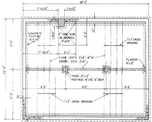
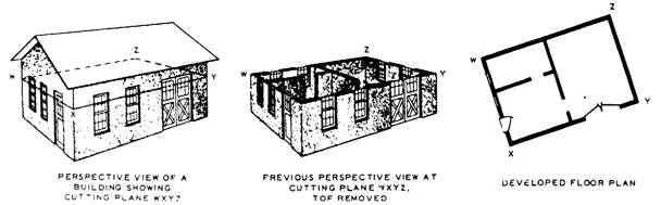
LAYOUT DRAWINGS Layout drawings are also called general plans and profile drawings. They provide the necessary information on the location, alignment, and elevation of the structure and its principal parts in relation to the ground at the site. They also provide other important details, such as the nature of the underlying soil or the location of adjacent structures and roads. These drawings are supplemented by instructions and information known as written specifications. GENERAL PLANS General plans contain information on the size, material, and makeup of all main members of the structure, their relative position and method of connection, as well as the attachment of other parts of the structure. The number of general plan drawings supplied is determined by such factors as the size and nature of the structure, and the complexity of operations. General plans consist of plan views, elevations, and sections of the structure and its various parts. The amount of information required determines the number and location of sections and elevations. FABRICATION DRAWINGS Fabrication drawings, or shop drawings, contain necessary information on the size, shape, material, and provisions for connections and attachments for each member. This information is in enough detail to permit ordering the material for the member concerned and its fabrication in the shop or yard. Component parts of the members are shown in the fabrication drawing, as well as dimensions and assembly marks. ERECTION DRAWINGS Erection drawings, or erection diagrams, show the location and position of the various members in the finished structure. They are especially useful to personnel performing the erection in the field. For instance, the erection drawings supply the approximate weight of heavy pieces, the number of pieces, and other helpful data. FALSEWORK DRAWINGS The term falsework refers to temporary supports of timber or steel that sometimes are required in the erection of difficult or important structures. When falsework is required on an elaborate scale, drawings similar to the general and detail drawings already described may be provided to guide construction. For simple falsework, field sketches may be all that is needed. Construction drawings are those in which as much construction information as possible is presented graphically, or by means of pictures. Most construction drawings consist of orthographic views. General drawings consist of plans and elevations drawn on relatively small scale. Detail drawings consist of sections and details drawn on a relatively large scale; we will discuss detail drawing in greater depth later in this chapter. A plan view is a view of an object or area as it would appear if projected onto a horizontal plane passed through or held above the object area. The most common construction plans are plot plans (also called site plans), foundation plans, floor plans, and framing plans. We will discuss each of them in the following paragraphs. A plot plan shows the contours, boundaries, roads, utilities, trees, structures, and other significant physical features about structures on their sites. The locations of the proposed structures are indicated by appropriate outlines or floor plans. As an example, a plot may locate the comers of a proposed structure at a given distance from a reference or base line. Since the reference or base line can be located at the site, the plot plan provides essential data for those who will lay out the building lines. The plot also can have contour lines that show the elevations of existing and proposed earth surfaces, and can provide essential data for the graders and excavators. A foundation plan (fig. 7-9) is a plan view of a structure projected on a imaginary horizontal plane passing through at the level of the tops of the foundations. The plan shown in figure 7-9 tells you that the main foundation of this structure will consist of a rectangular 8-inch concrete block wall, 22 by 28 feet, centered on a concrete footing 10 inches wide. Besides the outside wall and footing, there will be two 12-inch square piers, centered on 18-inch square footings, and located 9 feet 6 inches from the end wall building lines. These piers will support a ground floor center-line girder. Figure 7-10 shows the development of a typical floor plan, and figure 7-11 shows the floor plan itself.
Figure 7-9.-Foundation plan.
Figure 7-10.-Floor plan development.
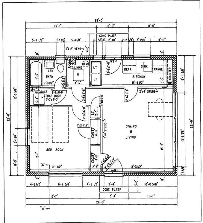
Figure 7-11.-Floor plan.
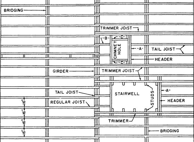
Figure 7-12.-Floor framing plan. Information on a floor plan includes the lengths, thicknesses, and character of the building walls on that particular floor, the widths and locations of door and window openings, the lengths and character of partitions, the number and arrangement of rooms, and the types and locations of utility installations. Framing plans show the dimension numbers and arrangement of structural members in wood-frame construction. A simple floor framing plan is superimposed on the foundation plan shown in figure 7-9. From this foundation plan you learn that the ground floor joists in this structure will consist of 2 by 8s, lapped at the girder, and spaced 16 inches on center (OC). The plan also shows that each row of joists is to be braced by a row of 1 by 3 cross bridges. More complicated floor framing problems require a framing plan like the one shown in figure 7-12. That plan, among other things, shows the arrangement of joists and other members around stairwells and other floor openings. A wall framing plan provides information similar to that in figure 7-11 for the studs, corner posts, bracing, sills, plates, and other structural members in the walls. Since it is a view on a vertical plane, a wall framing plan is not a plan in the strict technical sense. However, the practice of calling it a plan has become a general custom. A roof framing plan gives similar information with regard to the rafters, ridge, purlins, and other structural members in the roof. A utility plan is a floor plan that shows the layout of heating, electrical, plumbing, or other utility systems. Utility plans are used primarily by the ratings responsible for the utilities, and are equally important to the builder. Most utility installations require that openings be left in walls, floors, and roofs for the admission or installation of utility features. The builder who is placing a concrete foundation wall must study the utility plans to determine the number, sizes, and locations of openings he or she must leave for utilities. |
|
Privacy Statement - Press Release - Copyright Information. - Contact Us - Support Integrated Publishing |