 |
||
|
|
||
|
Page Title:
WELDED AND RIVETED STEEL STRUCTURES |
||
| |||||||||||||||
|
|
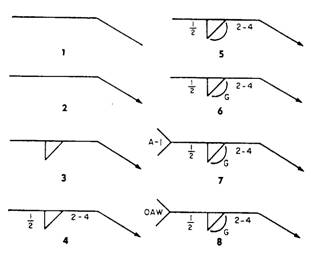
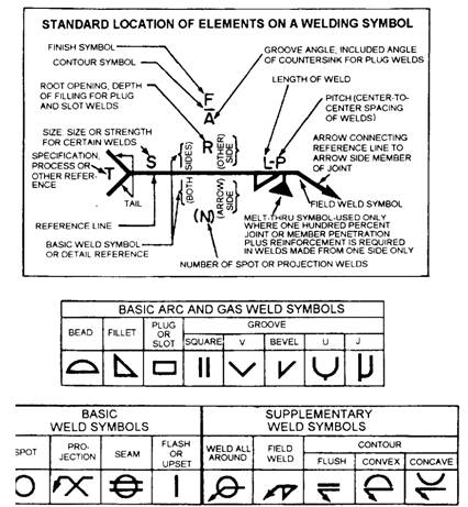
WELDED AND RIVETED STEEL STRUCTURES The following paragraphs will discuss welded and riveted steel structures and will give examples of both methods used to make trusses. WELDED STEEL STRUCTURES Generally, welded connections are framed or seated just as they are in riveted connections, which we will discuss later. However, welded connections are more flexible. The holes used to bolt or pin pieces together during welding are usually drilled in the fabrication shop. Beams are not usually welded directly to columns. The procedure produces a rigid connection and results in severe bending that stresses the beam, which must be resisted by both the beam and the weld. Welding symbols are a means of placing complete information on drawings. The top of figure 7-3 shows the welding symbol with the weld arrow. The arrow serves as a base on which all basic and supplementary symbol information is placed in standard locations. The assembled welding symbol is made up of weld symbols in their respective positions on the reference line and arrow, together with dimensions and other data (fig. 7-3). Look at figures 7-3 and 7-4 to help you read the eight elements of a welding symbol. Each element is numbered and illustrated separately in figure 7-4, and explained in the following paragraphs: 1. This shows the reference line, or base, for the other symbols. 2. This shows the arrow. The arrow points to the location of the weld.
Figure 7-4.-Elements of a welding symbol. 3. This shows the basic weld symbols. In this case it should be a fillet weld located on the arrow side of the object to be welded. 4. This shows the dimensions and other data. The 1/2 means the weld should be 1/2 inch thick, and
Figure 7-3.-Standard location of elements and types of welding symbols.
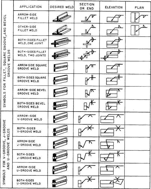
Figure 7-5.-Application of welding symbols. the 2-4 means the weld should be 2 inches long (L) with a center spacing or pitch (P) of 4 inches. 5. This shows the supplementary symbols. This supplementary symbol means the weld should be convex. 6. This shows the finish symbol, G, which means the weld should be finished by grinding. Note that the finish markings that show the degree of finish are different; they are explained in chapter 4. 7. This shows the tail. It is used to set off symbols that order the machinist to use a certain process or to follow certain specifications or other references; in this case, specification A-1. The tail will be omitted if it is not needed for this purpose. 8. This shows the specifications, process, or other reference explained in item 7. In this example, the tail of the symbol indicates the abbreviation of a process-oxyacetylene welding (OAW). (The abbreviation standards for every welding process are beyond the scope of this manual and have been omitted.) Figure 7-5 illustrates the various welding symbols and their application. |
|
Privacy Statement - Press Release - Copyright Information. - Contact Us - Support Integrated Publishing |