 |
||
|
|
||
| |||||||||||||||
|
|
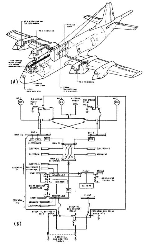
AIRCRAFT ELECTRICAL PRINTS Aircraft electrical prints include schematic diagrams and wiring diagrams. Schematic diagrams show electrical operations. They are drawn in the same manner and use the same graphic symbols from ANSI Y32.2 as shipboard electrical schematics. Aircraft electrical wiring diagrams show detailed circuit information on all electrical systems. A master wiring diagram is a single diagram that shows all the wiring in an aircraft. In most cases these would be so large as to be impractical; therefore, they are broken down into logical sections such as the do power system, the ac power system, and the aircraft lighting system. Diagrams of major circuits generally include an isometric shadow outline of the aircraft showing the location of items of equipment and the routing of interconnecting cables, as shown in figure 6-6, view
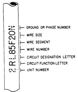
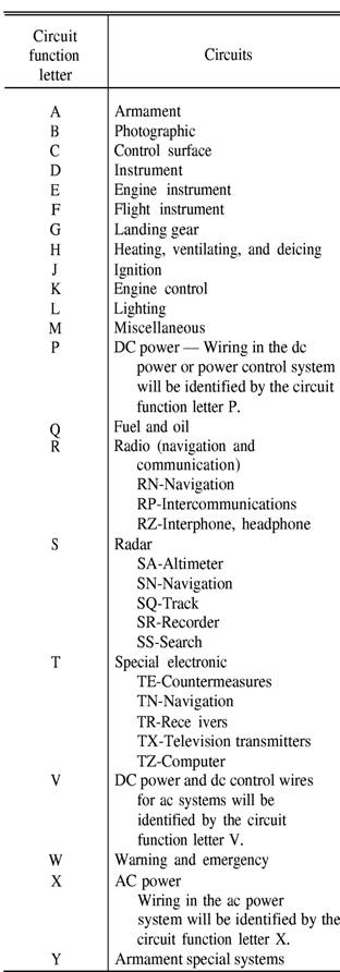
Figure 6-6.-Electrical power distribution in P-3A aircraft. A. This diagram is similar to a shipboard isometric wiring diagram. The simplified wiring diagram (fig. 6-6, view B) may be further broken down into various circuit wiring diagrams showing in detail how each component is connected into the system. Circuit wiring diagrams show equipment part numbers, wire numbers, and all terminal strips and plugs just as they do on shipboard wiring diagrams. Aircraft Wire Identification Coding All aircraft wiring is identified on the wiring diagrams exactly as marked in the aircraft. Each wire is coded by a combination of letters and numbers imprinted at prescribed intervals along the run. You need to look at figure 6-7 as you read the following paragraphs. The unit number shown dashed (fig. 6-7) is used only in those cases where more that one identical unit is installed in an identical manner in the same aircraft. The wiring for the first such unit would bear the prefix 1, the second unit the prefix 2, and so on. The rest of the designation remains the same in both units. The circuit function letter identifies the basic function of the unit concerned according to the codes shown in figure 6-8. Note the dashed L after the circuit function R in figure 6-7. On R, S, and T wiring, this letter designates a further breakdown of the circuit.
Figure 6-7.-Aircrafl wire identification.
Figure 6-8.-Aircraft wiring, circuit function code. |
|
Privacy Statement - Press Release - Copyright Information. - Contact Us - Support Integrated Publishing |