 |
||
|
|
||
| |||||||||||||||
|
|
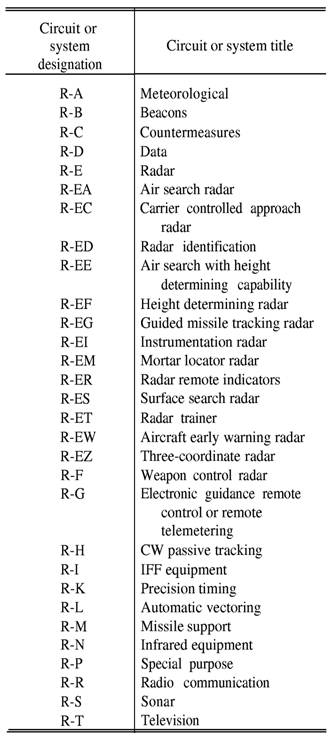
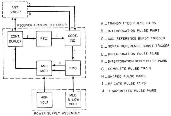
ELECTRONICS PRINTS Electronics prints are similar to electrical prints, but they are usually more difficult to read because they represent more complex circuitry and systems. This part of the chapter discusses common types of shipboard and aircraft electronic prints and basic logic diagrams. SHIPBOARD ELECTRONICS PRINTS Shipboard electronics prints include isometric wiring diagrams that show the general location of electronic units and the interconnecting cable runs, elementary wiring diagrams that show how each individual cable is connected, block diagrams, schematic diagrams, and interconnection diagrams. Cables that supply power to electronic equipment are tagged as explained in the electrical prints part of this chapter. However, cables between units of electronic equipment are tagged with electronic designations. Figure 6-9 shows a partial listing of these designations. The complete designation list (contained in NAVSHIPS 0967-000-0140), breaks down all system designation as shown for radar in figure 6-9. Cables between electronic units are tagged to show the system with which the cable is associated and the individual cable number. For example, in the cable marking R-ES4, the R identifies an electronic cable, ES identifies the cable as a surface search radar cable, and 4 identifies the cable number. If a circuit has two or more cables with identical designations, a circuit differentiating number is placed before the R, such as 1R-ES4, 2R-ES4, and so on. Block Diagrams Block diagrams describe the functional operation of an electronics system in the same way they do in electrical systems. In addition, some electronics block diagrams provide information useful in troubleshooting, which will be discussed later. A simplified block diagram is usually shown first, followed by a more detailed block diagram. Figure 6-10 shows a simplified block diagram of a shipboard tactical air navigation (TACAN) system. The TACAN system is an electronic air navigation system that provides a properly equipped
Figure 6-9.-Electronics circuit or system designations. aircraft with bearing and distance from a shipboard or ground radio beacon selected by the pilot. The system is made up of a radio beacon (consisting of the receiver-transmitter group, the antenna group, and the power supply assembly) and the radio set in the aircraft.
Figure 6-10.-Shipboard TACAN system, simplified block diagram. Figure 6-11 shows how the code indicator section would appear in a detailed block diagram for the TACAN system shown in figure 6-10. Note that this diagram shows the shape and amplitude of the wave forms at various points and the location of test points. Tube elements and pin numbers are also identified. For example, the interrogation reply pulse (top left corner of fig. 6-11) is applied to the grid (pin 7) of V604B, and the output from the cathode (pin 8) of V604B is applied to the grid (pin 2) of V611. Therefore, this kind of block diagram is sometimes called a servicing block diagram because it can be used to troubleshoot as well as identify function operations. Block diagrams that break down the simplified diagram into enough detail to show a fairly detailed picture of functional operation, but do not include wave forms, test points, and so on, are usually called functional block diagrams. Graphic electrical and electronic symbols are frequently used in functional and detailed block diagrams of electronic systems to present a better picture of how the system functions. Note the graphic symbol for the single-pole, two-position switch S603 at the bottom left corner in figure 6-11. Figure 6-12 shows other examples of graphic symbols in a block diagram. Detailed block diagrams of the type shown in figure 6-12 can be used to isolate a trouble to a particular assembly or subassembly. However, schematic diagrams are required to check the individual circuits and parts. |
|
Privacy Statement - Press Release - Copyright Information. - Contact Us - Support Integrated Publishing |