 |
||
|
|
||
| |||||||||||||||
|
|
OLD CABLE TAG SYSTEM. In the old system, the color of the tag shows the cable classification: red vital, yellow semivital, and gray or no color-nonvital. The tags will contain the following basic letters that designate power and lighting cables for the different services:
Figure 6-1.-Cable tag. Other letters and numbers are used with these basic letters to further identify the cable and complete the designation. Common markings of a power system for successive cables from a distribution switchboard to load would be as follows: feeders, FB-411; main, 1-FB-411; submain, 1-FB-411A; branch, 1-FB-4llAl; and sub-branch, 1-FB-411-AlA. The feeder number 411 in these examples shows the system voltage. The feeder numbers for a 117- or 120-volt system range from 100 to 190; for a 220-volt system, from 200 to 299; and for a 450-volt system, from 400 to 499. The exact designation for each cable is shown on the ship's electrical wiring prints. NEW CABLE TAG SYSTEM.-The new system consists of three parts in sequence; source, voltage, and service, and where practical, destination. These parts are separated by hyphens. The following letters are used to designate the different services:
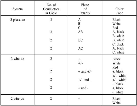
Voltages below 100 are designated by the actual voltage; for example, 24 for a 24-volt circuit. For voltages above 100, the number 1 shows voltages between 100 and 199; 2, voltages between 200 and 299; 4, voltages between 400 and 499, and so on. For a three-wire (120/240) do system or a three-wire, three-phase system, the number shows the higher voltage. The destination of cable beyond panels and switchboards is not designated except that each circuit alternately receives a letter, a number, a letter, and a number progressively every time it is fused. The destination of power cables to power-consuming equipment is not designated except that each cable to such equipment receives a single-letter alphabetical designation beginning with the letter A. Where two cables of the same power or lighting circuit are connected in a distribution panel or terminal box, the circuit classification is not changed. However, the cable markings have a suffix number in parentheses indicating the section. For example, figure 6-1 shows that (4-168-1)-4P-A(1) identifies a 450-volt power cable supplied from a power distribution panel on the fourth deck at frame 168 starboard. The letter A shows that this is the first cable from the panel and the (1) shows that it is the first section of a power main with more than one section. The power cables between generators and switchboards are labeled according to the generator designation. When only one generator supplies a switchboard, the generator will have the same number as the switchboard plus the letter G. Thus, 1SG identifies one ship's service generator that supplies the number 1 ship's service switchboard. When more than one ship's service generator supplies a switchboard, the first generator determined according to the general rule for numbering machinery will have the letter A immediately following the designation. The second generator that supplies the same switchboard will have the letter B. This procedure is continued for all generators that supply the switchboard, and then is repeated for succeeding switchboards. Thus, 1SGA and 1SGB identify two service generators that supply ship's service switchboard 1S. Phase and Polarity Markings Phase and polarity in ac and do electrical systems are designated by a wiring color code as shown in table 6-1. Neutral polarity, where it exists, is identified by the white conductor. Isometric Wiring Diagram An isometric wiring diagram is supplied for each shipboard electrical system. If the system is not too large, the diagram will be on one blueprint while larger systems may require several prints. An isometric wiring diagram shows the ship's decks arranged in tiers. It shows bulkheads and compartments, a marked centerline, frame numbers usually every five frames, and the outer edge of each deck in the general outline of the ship. It shows all athwartship lines at an angle of 30 degrees to the centerline. Cables running from one deck to another are drawn as lines at right angles to the centerline. A single line represents a cable regardless of the number of conductors. The various electrical fixtures are identified by a symbol number and their general location is shown. Therefore, the isometric wiring diagram shows a rough picture of the entire circuit layout. "Figure 6-2 (four pages at the end of this chapter) shows an isometric diagram of a section of the ship's service and emergency lighting system for a DLG." This figure shows the forward quarter of the decks concerned, whereas the actual blueprint will show the entire decks. Note the reference to another isometric diagram at the top of the figure. It shows that the diagram of the complete lighting system for this ship required two blueprints. All electrical fittings and fixtures shown on the isometric wiring diagram are identified by a symbol number as stated previously. The symbol number is taken from the Standard Electrical Symbol List, NAVSHIPS 0960-000-4000. This publication contains a complete list of standard symbol numbers for the various standard electrical fixtures and fittings for shipboard applications. For example, look at the distribution box symbol 615 located on the second platform starboard at frame 19 (fig. 6-2). It is identified in NAVSHIPS 0960-000-4000 as a type D-62A fourcircuit distribution box with switches and midget fuses. Its federal stock number is 6110-152-0262. Cables shown on the isometric wiring diagram are identified by the cable marking system described earlier in this chapter. In addition, cable sizes are shown in circular mils and number of conductors. Letters show the number of conductors in a cable; S for one-, D for Table 6-1.-Color Code for Power and Lighting Cable Conductors
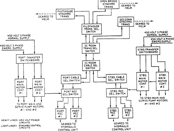
two-, T for three-, and F for four-conductor cables. The number following this letter denotes the wire's circular mil area in thousands. For example, the cable supplying distribution box symbol 615 (fig. 6-2) is marked (2-38-1)-L-Al-T-g. This marking identifies a three-conductor, 9000-circular mil, 120-volt, ship's service submain lighting cable supplied from panel 2-38-1. Note that you would need the isometric wiring diagram for the main deck and above to follow the complete run of this cable. This print would show lighting main 2(38-1)-1L-A-T-30 supplying a distribution box somewhere on the main deck (or above), and submain cable (2-38-1)-IL-Al-T-9 coming from this distribution box to supply distribution box symbol 615 on the second platform, frame 19 starboard. Remember, the isometric wiring diagram shows only the general location of the various cables and fixtures. Their exact location is shown on the wiring plan discussed briefly in the next paragraphs. Wiring Deck Plan The wiring deck plan is the actual installation diagram for the deck or decks shown and is used chiefly in ship construction. It helps the shipyard electrician lay out his or her work for a number of cables without referring to individual isometric wiring diagrams. The plan includes a bill of material that lists all materials and equipment necessary to complete installation for the deck or decks concerned. Equipment and materials except cables are identified by a symbol number both on the drawing and in the bill of material. Wiring deck plans are drawn to scale (usually 1/4 inch to the foot), and they show the exact location of all fixtures. One blueprint usually shows from 150 to 200 feet of space on one deck only. Electrical wiring equipment symbols from MIL-STD-15-2 are used to represent fixtures just as they do in the isometric wiring diagram. Elementary Wiring Diagram These diagrams show in detail each conductor, terminal, and connection in a circuit. They are used to check for proper connections in circuit or to make the initial hookup. In interior communication (IC) circuits, for example, the lugs on the wires in each connection are stamped with conductor markings. The elementary wiring diagrams show these conductor markings alongside each conductor and how they connect in the circuit. Elementary wiring diagrams usually do not show the location of connection boxes, panels, and so on; therefore, they are not drawn to any scale. Electrical System Diagrams Navy ships have electrical systems that include many types of electrical devices and components. These devices and components may be located in the same section or at various locations throughout the ship. The electrical diagrams and drawings necessary to operate and maintain these systems are found in the ship's electrical blueprints and in drawings and diagrams in NAVSHIPS' and manufacturers' technical manuals. BLOCK DIAGRAM.-These diagrams of electrical systems show major units of the system in block form. They are used with text material to present a general description of the system and its functions. Figure 6-3 shows a block diagram of the electrical steering system for a large ship. Look at the diagram along with the information in the following paragraphs to understand the function of the overall system. The steering gear system (fig. 6-3) consists of two similar synchro-controlled electrohydraulic systems; one for each rudder (port and starboard). They are separate systems, but they are normally controlled by the same steering wheel (helm) and they move both port and starboard rudders in unison. Each port and starboard system has two 100 hp main motors driving a variable-stroke pump through reduction gears. Each also has two 5-hp servo pump motors interconnected electrically with the main pump motors so both operate simultaneously. During normal operation, one main pump motor and one servo pump motor are used with the other units on standby. If the normal power supply fails, both port and starboard transfer switchboards may be transferred to an emergency 450-volt supply. The steering system may be operated from any one of three steering stations located in the pilothouse, at a secondary corn, and on the open bridge. A transmitter selector switch in the IC room is used to assign steering control to any of the three. To transfer steering control from the pilothouse to the open bridge station, the selector switch in the IC room must be in the pilothouse position. Duplicate power and control cables (port and starboard) run from a cable selector in the IC room to port and starboard cable selector switches in the steering gear room. From these switches, power and control cables connect to receiver selector switches. These selector switches allow selection of the appropriate synchro receiver for the system in operation.
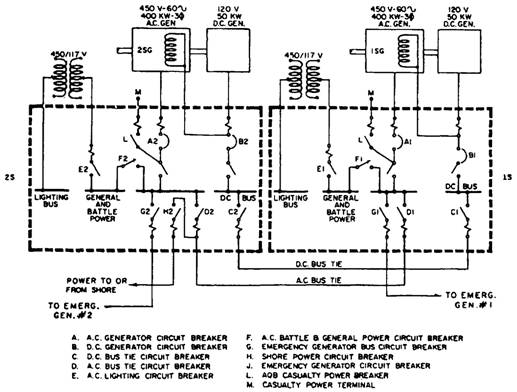
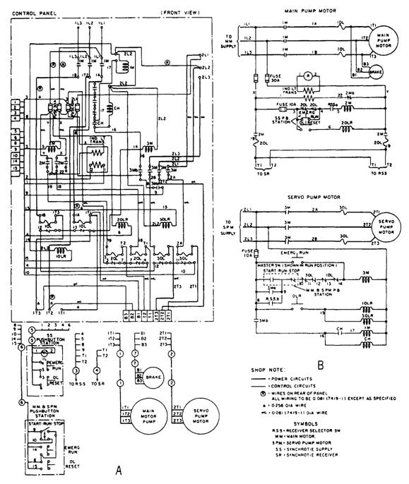
Figure 6-3.-Steering system block diagram. The following paragraphs explain a normal operating setup for pilothouse steering control of the complete system. PORT SYSTEM-Main and servo pump motors #2 operating; port receiver selector switch to #2 position, steering gear port cable select switch to the port cable position; IC cable selector switch (port system section) to the port cable position; and IC and pilothouse transmitter selector switches to the pilothouse position. STARBOARD SYSTEM-Main and servo pump motors #1 operating; starboard receiver selector switch to the #1 position; steering gear starboard cable selector switch to the starboard cable position; and IC cable selector switch (starboard system section) to the starboard cable position. When the control switches are set up in this manner, the motor and stator leads of the synchro transmitter at the pilothouse steering station are paralleled with the rotor and stator leads of the starboard #1 and port #2 synchro receivers in the steering gear room. 450 volts single phase is applied to the stator leads from main motor controllers #1 and #2. (The synchros have two stator and three rotor leads.) Due to synchro action, the receiver rotors will now follow all movements of the transmitter rotor and thus actuate the hydraulic system to move the rudders in response to the helm. SINGLE-LINE DIAGRAM.-This type of diagram shows a general description of a system and how it functions. It has more detail than the block diagram; therefore, it requires less supporting text. Figure 6-4 shows a single-line diagram of the ship's service generator and switchboard connections for a destroyer. It shows the type of ac and do generators used to supply power for the ship. It also shows in simplified form actual switching arrangements used to parallel the generators, to supply the different power lighting busses, and to energize the casualty power terminals. EQUIPMENT WIRING DIAGRAM.-Earlier in this chapter, we said a block diagram is useful to show the functional operation of a system. However, to troubleshoot a system, you will need wiring diagrams for the various equipments in the system. The wiring diagram for a particular piece of electrical equipment shows the relative position of the various components of the equipment and how each individual conductor is connected in the circuit. Some examples are coils, capacitors, resistors, terminal strips, and so on. Figure 6-5, view A, shows the main motor controller wiring diagram for the steering system shown in figure 6-3. This wiring diagram can be used to troubleshoot, check for proper electrical connections, or completely rewire the controller. SCHEMATIC DIAGRAM.-The electrical schematic diagram describes the electrical operation of a particular piece of equipment, circuit, or system. It is not drawn to scale and usually does not show the relative positions of the various components. Graphic symbols from ANSI Y32.2 represent all components. Parts and connections are omitted for simplicity if they are not essential to show how the circuit operates. Figure 6-5, view B, shows the schematic diagram for the steering system main motor controller that has the following electrical operation: Assume 450-volt, 3-phase power is available on lines 1L1, 1L2, and 1L3; and 2L1, 2L2 and 2L3; and the receiver selector is set so that the motors are to idle as standby equipment. Then turn the master switch (MM and SPM push-button station) to the start position to energize coil 3M. Coil 3M will close main line contacts 3M, starting the servo pump motor. When contacts 3M close, auxiliary contacts 3Ma and 3Mb also close. Contacts 3Ma shunt (bypass) the master switch start contacts to maintain power to coil 3M after the master switch is released. When released, the master switch spring returns to the run position, closing the run contacts and opening the start contacts. Turning the switch to the stop position opens the run contacts. Contacts 3Mb energize latching coil CH, closing contacts CH, and energizing coil 1M, which closes main line contacts 1M to start the main pump motor. (Solenoid latch CH prevents contacts 1M from opening or closing due to high-impact shock.) Before the motors can deliver steering power, the receiver selector switch must be set to the appropriate receiver, closing contacts RSSa and RSSb. Contacts RSSa energize coil 2M, which closes contacts 2M to supply single-phase power to the synchro system. Contacts RSSb shunt the start and 3Ma contacts so that in case of a power failure the motors will restart automatically upon restoration of power. In case of overload on the main or servo pump motor (excessive current through IOL or 30L), overload contacts IOL or 30L will open, de-energizing coil 3M to open line contacts 3M and stop the servo pump motor. When line contacts 3M open, contacts 3Ma and 3Mb open, deenergizing
Figure 6-4.-Ship's service generator and switchboard interconnections, single-line diagram.
Figure 6-5.-Main motor controller. A. Wiring diagram. B. Schematic. latching coil CH, and opening contacts CH. The opening of contacts CH de-energizes coil IM, which opens contacts IM to stop the main motor. If an overload occurs in the synchro supply circuit (excessive current through 20L), contacts 20L will open, deenergizing coil 2M to open contacts 2M. The overloads are reset after tripping by pressing the overload reset buttons. The equipment may be operated in an overloaded condition by pressing the emergency run buttons to shunt the overload contacts. |
|
Privacy Statement - Press Release - Copyright Information. - Contact Us - Support Integrated Publishing |