Custom Search
|
|
  |
|
|
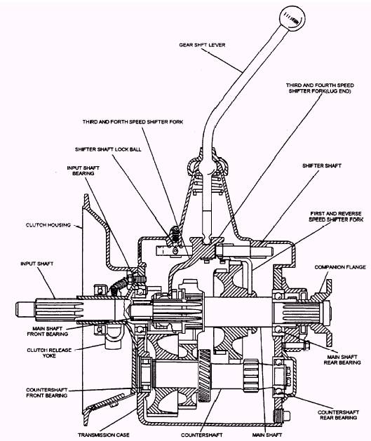
There are two types of shift linkages used on manual transmissions. They are the EXTERNAL ROD and the INTERNAL SHIFT RAIL. They both perform the same function. They connect the shift lever with the shift fork mechanism. The transmission shift lever assembly can be moved to cause movement of the shift linkage, shift forks, and synchronizers. The shift lever may be either floor mounted or column mounted, depending upon the manufacturer. Floor-mounted shift levers are generally used with an internal shift rail linkage, whereas column-mounted shift levers are generally used with an external rod linkage. TRANSMISSION TYPES The constant mesh transmission has parallel shafts with gears in constant mesh. Shifting is done by locking free-running gears to their shaft by using sliding collars. The synchromesh transmission also has gears in constant mesh. However, gears can be selected without clashing or grinding by synchronizing the speeds of the mating part before they engage. The sliding gear transmission is generally used in farm and industrial machines; therefore, we will only look closely at the constant mesh and synchromesh transmissions. Constant Mesh Transmission
Figure 4-18.- Constant mesh transmission assembly. The following is an example of the operation of a constant mesh transmission: When the shift lever is moved to THIRD, the THIRD and FOURTH shifter fork moves the sliding collar toward the THIRD speed gear. This engages the external teeth of the sliding collar with the internal teeth of the THIRD speed gear. Since the THIRD speed gear is meshed and rotating with the countershaft, the sliding collar must also rotate. The sliding collar is splined to the main shaft, and therefore, the main shaft rotates with the sliding collar. This principle is carried out when the shift lever moves from one speed to the next. The synchronizer accelerates or slows down the rotation of the shaft and gear, until both are rotating at the same speed and can be locked together without a gear clash. Since the vehicle is normally standing still when it is shifted into reverse gear, a synchronizer is not ordinarily used on the reverse gear. |
|
|
|