Custom Search
|
|
  |
|
|
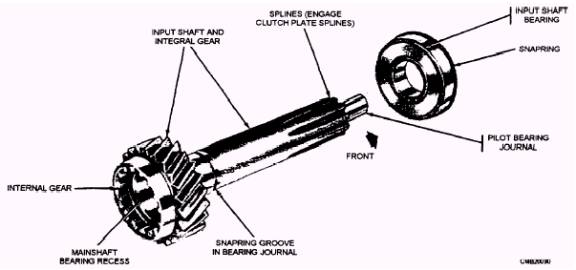
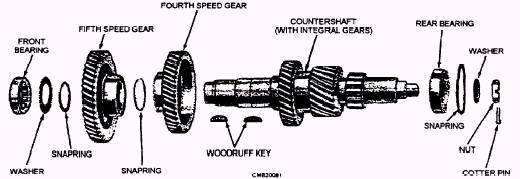
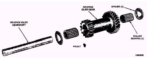
Transmission gears can be classified into four groups- input gear, countershaft gears, main shaft gears, and the reverse idler gear. The input gear turns
Figure 4-13.- Transmission input shaft and bearing.
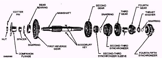
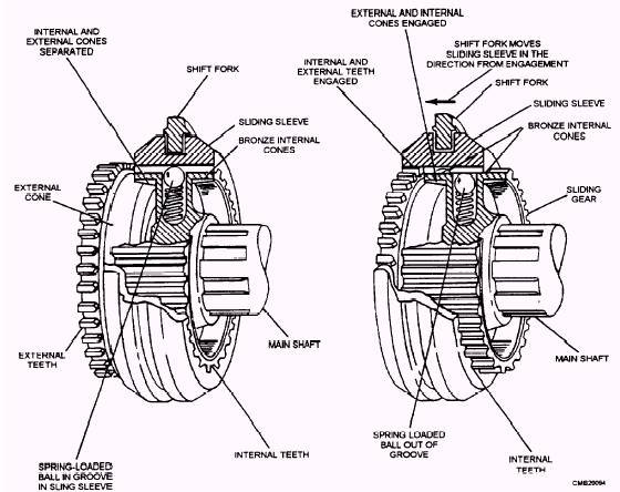
the countershaft gears, the countershaft gears turns the main shaft gears, and, when engaged, the reverse idler gear. In low gear, a small gear on the countershaft drives a larger gear on the main shaft, providing for a high gear ratio for accelerating. Then, in high gear, a larger countershaft gear turns a small main shaft gear or a gear of equal size, resulting in a low gear ratio, allowing the vehicle to move faster. When reverse is engaged, power flows from the countershaft gear, to the reverse idler gear, and to the engaged main shaft gear. This action reverses main shaft rotation. Synchronizers 1. Lock the main shaft gear to the main shaft. 2. Prevent the gear from clashing or grinding during shifting. When the synchronizer is moved along the main shaft, the cones act as a clutch. Upon touching the gear that is to be engaged, the main shaft is acceler-ated or slowed down until the speeds of the main shaft and gear are synchronized. This action occurs during partial movement of the shift lever. Com-pletion of lever movement then slides the sleeve and gear into complete engagement. This action can be readily understood by remembering that the hub of the sleeve slides on the splines of the main shaft to engage the cones; then the sleeve slides on the hub to engage the gears. As the synchronizer is slid against a gear, the gear is locked to the synchronizer and to the main shaft. Power can then be sent out of the transmission to the wheels. Shift Forks
Figure 4-17.- Synchronizers. linkage. The shift fork sets in a groove cut into the synchronizer sleeve. The linkage rod or shifting rail connects the shift fork to the operator's shift lever. As the lever moves, the linkage or rail moves the shift fork and synchronizer sleeve to engage the correct transmission gear. |
|
|
|