Custom Search
|
|
  |
|
|
Most fuel gauges are operated electrically and are composed of two units- the gauge, mounted on the instrument panel; and the sending unit, mounted in the fuel tank. The ignition switch is included in the fuel gauge circuit, so the gauge operates only when the ignition switch is in the ON position. Operation of the electrical gauge depends on either coil action or
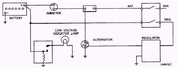
Figure 2-75.- Low voltage warning lamp schematic.
thermostatic action. The four types of fuel gauges are as follows: The THERMOSTATIC FUEL GAUGE, SELF-REGULATING (fig. 2-77), contains an electrically heated bimetallic strip that is linked to a pointer. A bimetallic strip consists of two dissimilar metals that, when heated, expand at different rates, causing it to deflect or bend. In the case of this gauge, the deflection of the bimetallic strip results in the movement of the pointer, causing the gauge to give a reading. The sending unit consists of a hinged arm with a float on the end. The movement of the arm controls a grounded point that makes contact with another point which is attached to an electrically heated bimetallic strip. The heating coils in the tank and the gauge are connected to each other in series. The THERMOSTATIC FUEL GAUGE, EXTERNALLY REGULATED (fig. 2-78), differs from a self-regulating system in the use of a variable resistance fuel tank sending unit and an external voltage-limiting device. The sending unit controls the gauge through the use of a rheostat (wire wound resistance unit whose value varies with its effective length). Theeffective length of the rheostat is controlled in the sending unit by a sliding brush that is operated by the float arm. The power supply to the gauge is kept constant through the use of a voltage limiter. The voltage limiter consists of a set of contact points that are controlled by an electrically heated bimetallic arm. The THERMOSTATIC FUEL GAUGE, DIFFERENTIAL TYPE (fig. 2-79), is similar to the other type of thermostatic fuel gauges, except that it uses two electrically heated bimetallic strips that share equally in operating and supporting the gauge pointer. The MAGNETIC FUEL GAUGE (fig. 2-80) consists of a pointer mounted on an armature. Depending upon the design, the armature may contain one or two poles. The gauge is motivated by a magnetic field that is created by two separate magnetic coils that
Figure 2-78.- Thermostatic fuel gauge, externally regulated.
Figure 2-79.- Thermostatic fuel gauge, differential type. are contained in the gauge. One of these coils is connected directly to the battery, producing a constant magnetic field. The other coil produces a variable field, whose strength is determined by a rheostat-type tank unit. The coils are placed 90 degrees apart. A pressure gauge is used widely in automotive and construction applications to keep track of such things as oil pressure, fuel line pressure, air brake system
Figure 2-80.- Magnetic fuel gauge. pressure, and the pressure in the hydraulic systems. Depending on the equipment, a mechanical gauge, an electrical gauge, or an indicator lamp may be used. The MECHANICAL GAUGE (fig. 2-81) uses a thin tube to carry an actual pressure sample directly to the gauge. The gauge basically consists of a hollow, flexible C-shaped tube, called a bourbon tube. As air or fluid pressure is applied to the bourbon tube, it will tend to straighten out. As it straightens, the attached pointer will move, giving a reading. The ELECTRIC GAUGE may be of the thermostatic or magnetic type as previous discussed. The sending unit (fig. 2-82) that is used with each gauge type varies as follows: 1. The sending unit that is used with the thermostatic pressure gauge uses a flexible diaphragm that moves a grounded contact. The contact that mates with the grounded contact is attached to a bimetallic strip. The flexing of the diaphragm, which is done with pressure changes, varies the point tension. The different positions of the diaphragm produce gauge readings.
Figure 2-81.- Mechanical pressure gauge. 2. The sending unit that is used with the magnetic-type gauge also translates pressure into the flexing of a diaphragm. In the case of the magnetic gauge sending unit, however, the diaphragm operates a rheostat. The INDICATOR LAMP (warning light) is used in place of a gauge on many vehicles. The warning light, although not an accurate indicator, is valuable because of its high visibility in the event of a low-pressure condition. The warning light receives battery power through the ignition switch. The circuit to ground is completed through a sending unit. The sending unit consists of a pressure-sensitive diaphragm that operates a set of contact points that are calibrated to turn on the warning light whenever pressure drops below a set pressure. |
|
|
|