Custom Search
|
|
  |
|
|
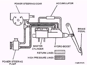
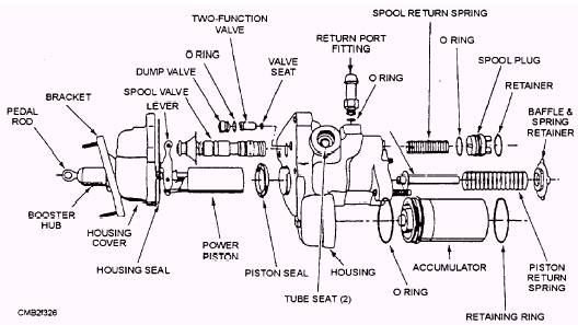
The hydraulic-power booster, also called a hydroboost (fig. 7-24), is attached directly to the master cylinder and uses power steering pump pressure to assist the operator in applying the brake pedal. The hydraulic booster contains a spool valve that has an open center that controls the pump pressure as braking occurs. A lever assembly has control over the valve position and the boost piston provides the necessary force that operates the master cylinder. See figure 7-25 for a parts breakdown of a booster assembly. The hydroboost system has an accumulator built into the system. The accumulator, which is either spring-loaded or pressurized gas, is filled with fluid and pressurized whenever the brakes are applied. Should the power steering system fail because of lack of fluid or a broken belt, the accumulator will retain enough fluid and pressure for at least two brake applications. PARKING BRAKES
Figure 7-24.- Hydraulic power booster system.
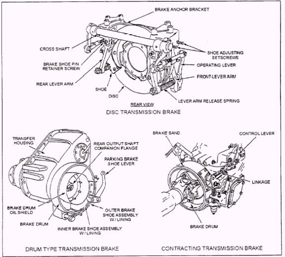
Several types of parking/ emergency brakes are manufactured for construction equipment, such as the external contracting, the drum, and the disc types (fig. 7-28). These are drive line brakes common to heavy construction equipment. They are usually mounted on the output shaft of the transmission or transfer case directly in the drive line.
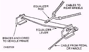
Figure 7-27.- Equalizer linkage. Theoretically, this type of system is preferred for heavy equipment because the braking force is multiplied through the drive line by the final drive ratio. Also, braking action is equalized perfectly through the differential. There are some drawbacks to this system, however- severe strain is placed on the transmission system, and also the vehicle may move when being lifted since the differential is not locked out.
Figure 7-28.- Examples of drive line parking/ emergency brakes, transmission mounted. |
|
|
|