Custom Search
|
|
  |
|
|
Power brakes systems are designed to reduce the effort required to depress the brake pedal when stopping or holding a vehicle stationary. The booster is located between the brake pedal linkage and the master cylinder. Most power brake systems use the difference between intake manifold vacuum and atmospheric pressure to develop the additional force required to apply the brakes. When the operator depresses the brake pedal, the power booster increases the amount of pressure applied to the piston within the master cylinder without the operator having to greatly increase brake pedal pressure. When a vehicle is powered by a diesel engine, the absence of intake manifold vacuum requires the use of an auxiliary vacuum pump. This pump may be driven by the engine or by an electric motor. Vacuum Boosters A vacuum booster consists of a round enclosed housing and a diaphragm. The power brake vacuum booster uses engine vacuum (or vacuum pump action on a diesel engine) to apply the hydraulic brake system. Vacuum boosters are classified into two types (fig. 7-22)- atmospheric suspended and vacuum suspended. The descriptions of the two types are as follows: An atmospheric suspended brake booster (fig. 7-22) has normal air pressure on both sides of the diaphragm when the brake pedal is released. As the brakes are applied, a vacuum is formed in one side of the booster. Atmospheric pressure then pushes on and moves the diaphragm. An vacuum suspended brake booster (fig. 7-22) has vacuum on both sides of the diaphragm when the brake pedal is released. Pushing down on the brake pedal releases vacuum on one side of the booster. The difference in air pressure pushes the diaphragm for braking action. Air has a weight of approximately 15 pounds per square inch at sea level. The weight of the air or atmospheric pressure is what is used to operate the vacuum booster.
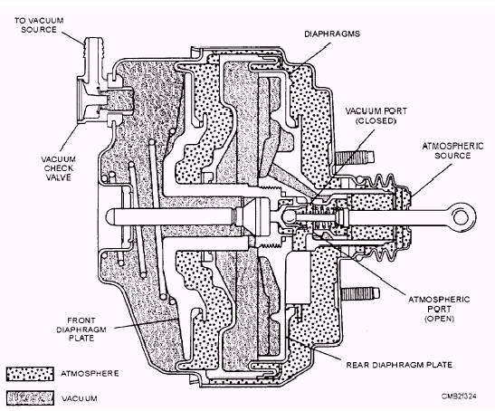
Figure 7-22.- Vacuum power booster and operation. It is impossible to create a perfect vacuum, but by were suddenly opened, outside air would rush into the pumping air from a container, it is possible to obtain a container to equalize the pressure. It is upon this difference in pressure between the outside and inside principle that the power cylinder of a vacuum booster of the container. or a partial vacuum. If the container system operates. The power brake operates during three phases of braking application- brakes released, brakes applied, and brakes holding. The operations of a typical vacuum-suspended power booster are as follows: RELEASED POSITION (fig. 7-22)- With the brakes fully released and the engine operating, the rod and plunger return spring moves the valve operating rod and valve plunger to the right. As this happens, the right end of the valve plunger is pressed against the face of the poppet valve, closing off the atmospheric port and opening the vacuum port. With the vacuum port opened, vacuum is directed to both sides of the diaphragm, and the return spring holds the diaphragm away from the master cylinder. APPLIED POSITION (fig. 7-22)- As the brake pedal is depressed, the valve operating rod moves to the left, which causes the valve plunger to move left also. The valve return spring is then compressed as the plunger moves and the poppet valve comes in contact with the vacuum port seat. As this happens, the vacuum port closes off. Continued application of the brake pedal causes the valve rod to force the valve plunger from the poppet, thereby opening the atmospheric port. Atmospheric pressure then rushes into the control vacuum chamber and applies pressure to the hydraulic pushrod. HOLDING POSITION (fig. 7-22)- As the operator stops depressing the brake pedal, the plunger will also stop moving. The reaction of the brake fluid transmitted through the reaction disc now will shift the valve plunger slightly to the right, shutting off the atmospheric port. As this position is held, both sides of the diaphragm contain unchanging amounts of pressure, which exerts a steady amount of pressure on the cylinder piston. On many installations a vacuum reservoir is inserted between the power booster and the intake manifold. The purpose of the reservoir is to make vacuum available for a short time to the booster unit should the vehicle have to stop quickly with a stalled engine. A check valve in the reservoir maintains a uniform vacuum within the system should engine vacuum drop off. This check valve prevents vacuum from bleeding back to the intake manifold when manifold vacuum is less than the vacuum in the reservoir. All modern power brakes retain some pedal resistance, permitting the operator to maintain a certain amount of pedal feel. For example, a light pressure upon the pedal will give a light braking force, while heavy pressure upon the brake pedal will cause severe brake application. If the vacuum section of the power booster should fail, brake application can still be obtained by direct mechanical pressure on the master cylinder piston. However, the operator must apply a greater force to the brake pedal to achieve even minimal braking force. The vacuum-hydraulic power booster, used in most passenger vehicles and light trucks, is of the integral type, so-called because the power booster and the master cylinder are combined in a single assembly. The most common integral types all use a single or tandem diaphragm (fig. 7-23) and are of the vacuum suspended type. The power unit uses a master cylinder constructed in the same manner as the conventional dual master cylinder. If brake trouble is encountered, check the brake system in the same manner as for conventional brakes. When a vehicle has vacuum type power brakes, you should inspect the brake booster and vacuum hose. Make sure the vacuum hose from the engine is in good condition. It should not be hardened, cracked, or swollen. Also check the hose fitting in the booster. If the system is not performing properly, you should check the power booster for correct operation as follows: Stop the engine and apply the brakes several times to deplete the vacuum reserve in the system. Partly depress the brake pedal, and while holding it in this position, start the engine. If the booster is operating properly, the brake pedal will move downward slightly. If no action is felt, the booster is not functioning. If the power unit is not giving enough assistance, check the engine vacuum. If engine vacuum is abnormally low (below 14 inches at idle), tune up the engine to raise the vacuum reading and again try the brakes. A steady hiss, when the brake pedal is depressed, indicates a vacuum leak, preventing proper operation of the booster. Vacuum failure, which results in a hard pedal, may be due to a faulty check valve, a collapsed vacuum hose to the intake manifold, or an internal leak in the power booster. A tight pedal linkage (insufficient pushrod clearance) will also result in a hard pedal. If this connection is free and the brakes still fail to release properly, the power booster must be replaced.
Figure 7-23.- Tandem-type booster. In addition to hydraulic system problems, the brakes may fail to release as a result of a blocked passage in the power piston, a sticking air valve, or a broken air valve spring. Any malfunction occurring in the power booster will require removing the booster from the vehicle for repair or replacement. Some power boosters may be rebuilt or repaired; others are sealed and cannot be disassembled. Should you have any questions concerning repairs on the power brake system you are working on, consult the manufacturer's service manual for proper procedures to follow when testing or repairing a unit. |
 |
|
|