Custom Search
|
|
  |
|
|
The conventional differential delivers the same amount of torque to each rear wheel when both wheels have equal traction. When one wheel has less traction than the other, for example, when one wheel slips on ice, the other wheel cannot deliver torque. All turning effort goes to the slipping wheel. To provide good even traction even though one wheel is slipping, a limited slip differential is used in many vehicles. It is very similar to the standard unit but has some means of preventing wheel spin and loss of traction. The standard differential delivers maximum torque to the wheel with minimum traction. The limited slip differential delivers maximum torque to the wheel with maximum traction. Other names for a limited slip
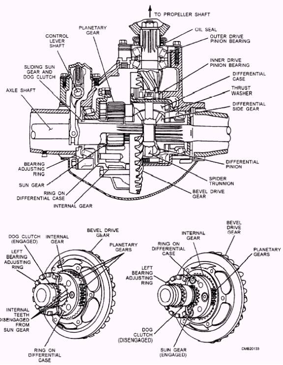
Figure 5-15.- Two speed final drive. Clutch Pack Limited Slip Differential Springs (bellville springs, coil springs, or leaf springs) force the friction disc and steel plates together. As a result, both rear axles try to turn with the differential case.
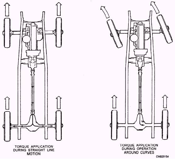
Figure 5-16.- Differential operation. Spring force and thrust action of the spider gears applies the clutch pack. Under high torque conditions, the rotation of the differential pinion gears PUSHES OUT on the axle side gears. The axle side gears then push on the clutch discs. This action helps lock the disc and keeps both wheels turning. However, when driving normally, the vehicle can turn a comer without both wheels rotating at the same speed. As the vehicle turns a comer, the inner drive wheel must slow down. The unequal speed between the side gears causes the side gear pinions to walk around the side gears. This walking will cause the outer axle shaft to rotate faster than the differential case, allowing the pinion shaft on the side to slide down a V-shaped ramp. This action releases the outer clutches causing the clutch pack to slip when the vehicle is turning.
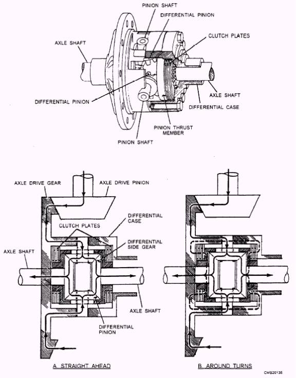
Figure 5-17.- Clutch pack limited slip differential. Under rapid acceleration or when one wheel loses traction. the differential pinion gears, as they drive the cones, push outward on the cone gears. This action increases friction between the cones and case, driving the wheels with even greater torque. When a vehicle goes around a comer, the inner drive wheel must slow down. The unequal speed between the side gears will cause the side gear pinions to walk around the side gears. This walking action causes the outer axle shaft to rotate faster than the differential case. Because the cones have spiral grooves cut into their clutch surfaces, the inner cone will draw itself into the case and lock tight and the outer cone clutch will back itself out of the case. This action allows the outer drive axle to free wheel. The end result is the majority of the engine torque is sent to the inner drive wheel. |
 |
|
|