Custom Search
|
|
  |
|
|
IMPROVED MULTIPLE EJECTOR RACK BRU-41/A
(IMER) AND IMPROVED TRIPLE EJECTOR RACK BRU-42/A (ITER) The BRU-41/A (fig. 10-23) and the BRU-42/A (fig. 10-24) operate and function basically the same. There are four major subassemblies-the structural adapter assembly, the electronic control unit, the cable assembly, and the ejector unit. The electronic control unit and the ejector unit are the same for both the BRU-41/A and the BRU-42/A.
Figure 10-24.-BRU-42/A ITER.
Figure 10-25.-IMER/ITER ejector unit locations.
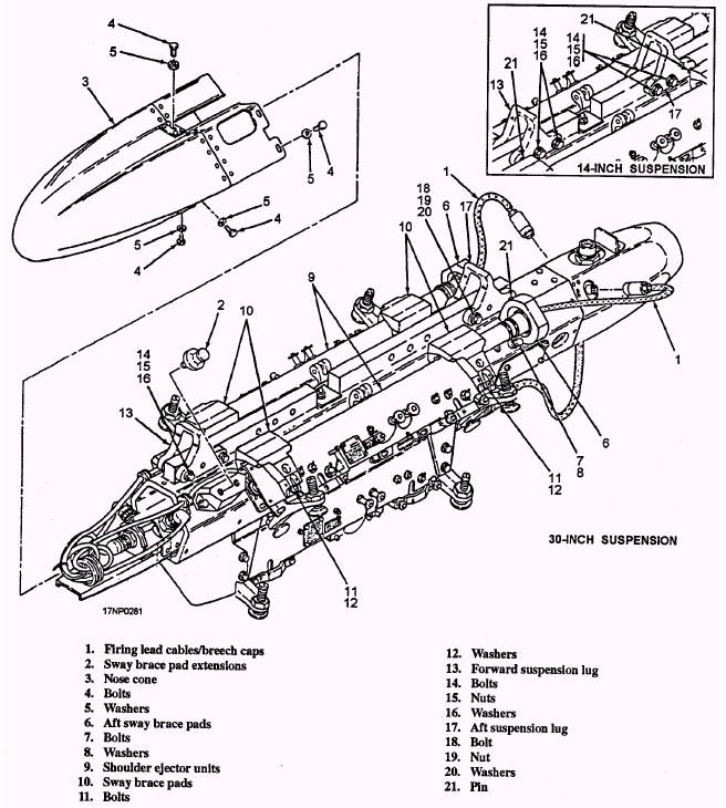
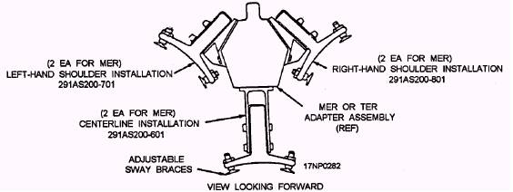
Figure 10-26.-IMER/ITER ejector unit. 10-20 Adapter Assembly The adapter assembly is a hollow, hexagonal aluminum extrusion that forms the main support for the rack assembly hardware. Attaching points on the adapter assembly provide 14-inch or 30-inch spacing of the suspension lugs, which allows installation on the various types of aircraft. The adapter assembly houses the electronic control unit and cable assembly and provides for attachment of six or three individual ejector units. A nose-cone assembly and a tail-cone assembly enclose the ends of the adapter assembly for aerodynamic purposes. Electronic Control Unit The electronic control unit is a solid-state electronic control unit in a sealed container. The electronic control unit controls all the functions of the bomb rack and has the capability of releasing stores at 35-millisecond intervals. The electronic control unit is disposable. If it malfunctions, replace it with a new one. The ejector unit assemblies used on the IMER and ITER are identical. The only difference between them is the internal configuration of the release linkage. The ejector units are configured for right-hand shoulder installation, left-hand shoulder installation, or centerline installation (fig. 10-25). They are identified by part number. The shoulder stations are attached to the adapter assembly by ejector unit attach blocks. The centerline stations are attached by ejector unit attach hangars. A IMER/ITER ejector unit (fig. 10-26) consists of a housing assembly equipped with integral wiring, a breech and ejector mechanism, store suspension hooks, a store sensing switch, two mechanical arming solenoids, an electrical arming unit, adjustable sway braces, and mechanical linkage driven by the breech or manual release lever to open the suspension hooks. The suspension hooks are spaced 14 inches apart and are independently self-latching. There is a manual release lever, which is used to open the hooks during ground operation. The safety stop lever is used to safe the ejector unit mechanically. Look at figure 10-27. It shows the locked and unlocked positions of the ejector unit safety stop lever. When the safety lever is in the locked position, the hook release rod is physically blocked from rearward movement and prevents suspension hook release. If the hook release rod is not in the full forward position, the safety stop lever cannot be rotated to the locked position. A store sensing switch is located under the forward suspension hook, and is actuated by the opening and closing of the hook. |
|
|
|