Custom Search
|
|
  |
|
|
IMER/ITER Operational Description The functional description of the IMER/ITER ejector rack is discussed in two categories-ejector unit mechanical operation and IMER/ITER electrical operation. EJECTOR UNIT OPERATIONAL DESCRIPTION.- All ejector units on the IMER and ITER are operationally the same. The ejection mechanism is actuated by an electrically initiated gas-generating cartridge. As you read this section, look
Figure 10-27.-Ejector unit safety stop lever.
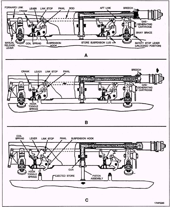
Figure 10-28.-Ejector unit operation. at figure 10-28. It shows the mechanical operation of the ejector unit. When a store is loaded onto the ejector unit, the store suspension lugs force the suspension hooks to the closed position. The suspension hooks are locked in the closed position by the overcenter position of the hook toggle levers. The link stops, located over each of the hook toggle levers, prevent the suspension hooks from opening until the cartridge is fired or the manual release lever is pulled, even if the safety stop lever is in the unlocked position (fig. 10-28, view A). When the gas-generating cartridge is fired, the resulting gas pressure moves the breech aft. The aft movement of the breech also moves the hook release rod aft, lifting the toggle hook levers from the overcenter position. The cranks are forced down. This unlocks the suspension hooks (fig. 10-28, view B). Gas pressure from the cartridge acting against the gun piston, plus the weight of the store, forces the unlocked suspension hooks to open, releasing the store. The hooks are held in the open position by the hook toggle spring and coil spring. The gun piston continues to act against the store to provide positive separation from the ejector unit (fig. 10-28, view C). IMER/ITER ELECTRICAL OPERATION.- Before discussing the electrical operation of the IMER/ITER, you must understand the function of several electrical components. These components are briefly discussed in the following paragraphs. IMER and ITER ejector units are numbered according to their firing sequence (fig. 10-29). For the purpose of discussion, assume that a IMER has stores loaded on stations 1, 2, 4, and 6, and that the release mode selector is set for single release. When the pilot depresses the cockpit bomb button, a firing pulse is routed from the aircraft through the rack safety switch and the release mode selector switch to energize the necessary rack circuits. With a weapon loaded on station 1, the forward suspension hook is in the closed position, automatically closing the stores sensing switch. The firing voltage is then routed to the firing circuit, firing the cartridge and ejecting the weapon. Ejection of the stores from all remaining loaded stations will occur in sequence each time the pilot presses and releases the bomb button. In this particular load, stations 3 and 5 were not loaded; therefore, make sure the forward hooks are left open. If they are closed, the stores sensing switch signals the rack that a weapon is loaded on that station and will not automatically step to the next station. Hardware Adapter Kits Hardware adapter kits are used to adapt the IMER/ITER to various aircraft. The kits include electrical harness assemblies, suspension lugs, sway brace pads and extensions, and attaching hardware required to configure the racks for a desired pylon station on a particular aircraft. Additionally, practice bomb adapters are used to adapt the IMER and ITER for the attachment of practice bombs or externally carried
Figure 10-29.-IMER/ITER firing sequence. 10-23
Figure 10-30.-Practice bomb adapter kit. Mk 45 aircraft parachute flares and Mk 58 marine location markers. The adapter (fig. 10-30) is composed of three separate components-a bracket, an ejector footlock, and a hook actuation spring. Both the hardware adapter kit and practice bomb adapter are considered to be organizational-level equipment, and are to be maintained in the custody of the organizational unit. For further information concerning the MER and TER, refer to the publication NAVAIR 11-75A-57, Multiple Ejector Rack (MER) A/A37B-6E and Triple Ejector Rack (TER) A/A37B-5E (latest revision). For the improved multiple ejector rack (IMER) and improved triple ejector rack (ITER), refer to the publication NAVAIR 11-5-603. |
 
|
|
|