Custom Search
|
|
  |
|
|
VOLTAGE TEST.- To perform a voltage test of the S-3 bleed-air shutoff valve, you must first secure power to the valve. Set the function switch of your multimeter to the + dc position. Set the range select switch to the 50V position. Next, insert the black test lead in the (-) common jack and the red lead in the ( + ) jack. Before proceeding, you should review the appropriate MIM for the correct placement of the test lead probes with respect to the connector pins. You should also review the voltage requirements for a successful test. Finally, you should ensure that all circuit breakers and switches are in the correct position. After applying power to the connector, be sure that you are using the correct meter scale to obtain the voltage reading. In this example, you would use the 50 dc scale. With the test completed, you should return to the MIM for the remainder of the steps in the troubleshooting procedure.
RESISTANCE TEST.- To perform a resist-ance check on an S-3 cabin temperature sensor you must secure power to it. Then, ground the sensor to remove any voltage that may remain in the circuit. Set the function switch to the + dc position. Set the range select switch to the R x 100 position. Next, insert the black test lead in the(-) common jack and the red lead in the ( + ) jack. With the power removed and the meter preset, short the test leads by touching them together. Then place the meter in a horizontal position and rotate the 0 ohms control until the meter indicates zero. It is important to keep the meter in the same position for the entire test to ensure accurate readings. NOTE: The function switch may have to be reset to keep the resistance reading near the mid-scale point. Because ambient temperature affects the resistance of the sensor, you should refer to the air temperature versus resistance schedule chart of the MIM to obtain the prescribed resistance readings. The MIM should also be consulted for the proper multimeter probe placement on the sensor. For this example, your resistance readings is read from the top scales (ohms) as shown in figure 3-24.
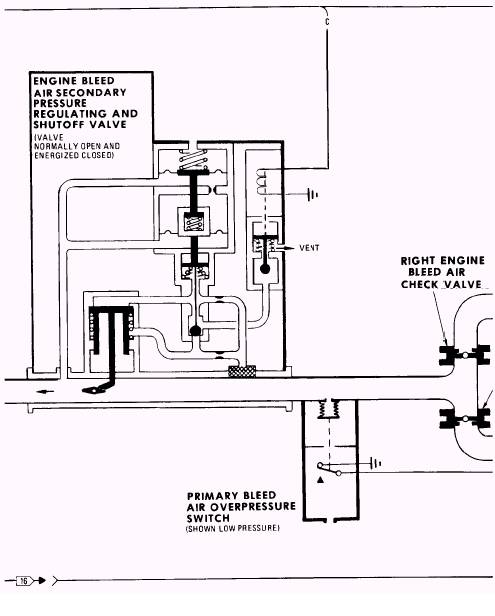
Figure 3-1A.- Bleed-air system.
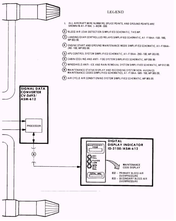
Figure 3-1B.- Bleed-air system-Continued
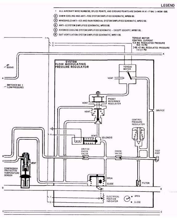
Figure 3-1C.- Bleed-air system-Continued
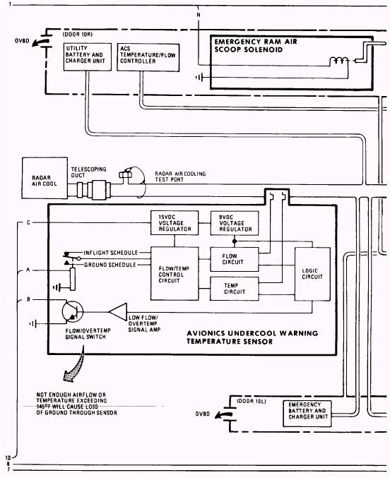
Figure 3-1D.- Bleed-air system-Continued
Figure 3-2A.- Air cycle air-conditioning system.
Figure 3-2B.- Air cycle air-conditioning system-Continued
Figure 3-2C.- Air cycle air-conditioning system-Continued
Figure 3-2D.- Air cycle air-conditioning system-Continued
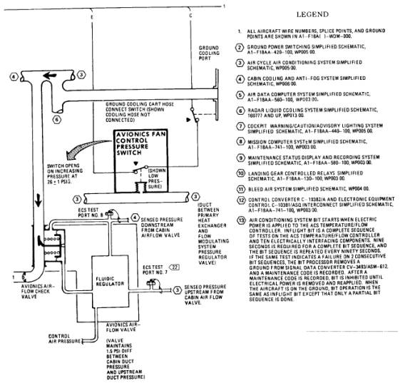
Figure 3-11A.- Avionics cooling system.
Figure 3-11B.- Avionics cooling system-Continued
Figure 3-11C.- Avionics cooling system-Continued
Figure 3-11D.- Avionics cooling system-Continued
|
 
|
|
|