Custom Search
|
|
  |
|
|
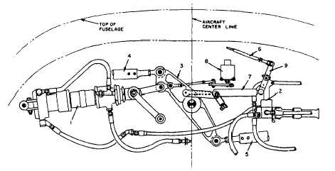
Proof-Testing Cables All newly fabricated cables should be tested for proper strength before they are installed in aircraft The test consists of applying a specified tension load on the cable for a specified number of minutes. The proof loads for testing various size cables are given in tables contained in NAVAIR 01-1A-8. Proof loading will result in a certain amount of permanent stretch being imparted to the cable. This stretch must be taken into account when You fabricate cable assemblies. Cables that are made up long slightly may be entirely too long after proof loading.SECONDARY FLIGHT CONTROL SYSTEMS Learning Objective: Recognize the varied functions of secondary flight control systems and the maintenance associated with each system.Secondary flight controls, such as wing flaps and speed brakes, are usually hydraulically operated and either mechanically or electrically controlled. The design of these flight controls slows the aircraft in flight and provides additional lift and stability. These design features greatly increase the versatility and performance of the aircraft.CONVENTIONAL WING FLAP SYSTEM A flap is a hinged or pivoted section that forms the rear portion of an airfoil used to vary the effective chamber. Wing flaps in their most commonly used form are hinged sections of the trailing edges of a wing. Flaps extend from the fuselage to the inboard side of the aileron. Wing flaps are connected to the main wing by various kinds of hinges and slides. The flap system discussed in this section is a representative system. The number of flaps will vary according to the size of the aircraft. The components may have different names, depending on the manufacturer, but the operational theory remains the same. This system consists of a series of six flaps, three on the trailing edge of each wing. They raise and lower in the conventional manner by a hydraulically actuated linkage of bell cranks, pushrods, and idlers. The flap control lever in the cockpit controls the system mechanically. The lever connects by conventional and teleflex cables to the hydraulic actuating mechanism. An emergency system is provided for lowering the flaps by operating a hand pump if the primary system malfunctions. The flap system has a position indicator and several safety devices to prevent lowering of the flaps while the wings are folded, or folding of the wings while the flaps are lowered.The movement of the flap selector lever in the cockpit sets the flaps in motion. Movement of the selector lever operates a cable quadrant to which a set of conventional control cables attach. These cables connect to another sector just forward of the main wing beam. A teleflex cable, also attached to this aft sector, and a spring-loaded pushrod on the main flap actuating bell crank connect to the two ends of a short floating arm installed on the hydraulic selector valve lever. Figure 9-32 is a drawing of the cylinder, linkage, and selector valve installation. Reference to the index numbers on this drawing is made in the following description of the operation of the flap control system.
Figure 9-32.Flap cylinder, linkage, and selector valve installation. When the flap handle in the cockpit moves down, the upper end of the floating arm (9) pulls to the left, pivoting at its lower end and moving the selector valve lever to the left. This action directs pressure from the hydraulic system to the flap actuating cylinder (1). The cylinder piston rod extends and lowers the flaps by rotating the flap drive bell crank (3) in a clockwise direction. As the bell crank moves, the lower end of the floating arm moves to the right by the spring-loaded pushrod (7). This action pivots the arm at its upper connection to the sector pushrod and returns the selector valve to neutral, stopping the action of the system. Moving the flap handle upward reverses the foregoing procedure by pushing the selector valve lever to the right, directing hydraulic pressure to the retract side of the cylinder piston and raising the flaps. The follow-up rod then moves the lower end of the floating arm to the left and returns the selector valve to neutral, The valve will not return completely to neutral, maintaining pressure in the flap cylinder and ensuring positive locking of the flaps in the up position. The spring mechanism in the follow-up rod normally does not function The spring mechanism is provided only as a safety feature, permitting actuation of the flap drive crank by emergency hydraulic power if the selector valve becomes jammed. The flap hydraulic system consists primarily of the selector valve and the actuating cylinder. See figure 9-33. The selector valve is a four-way, poppet-type valve. The poppets operate in pairs to direct pressure to one side of the cylinder while opening the other side to reservoir return. The cylinder is double acting and internally locked in the retracted (flaps up) position. The cylinder also has an integral shuttle valve (built into the mounting end cap). This provides for the separation between the normal and emergency hydraulic pressure lines. An adjustable terminal on the piston rod provides for length variation. When the cylinder extends, the internal lock is hydraulically released, allowing the piston to move. When the flaps raise, the hydraulic pressure on the lock is relieved, and a compression spring engages the lock mechanism with the piston when the cylinder becomes fully retracted. A relief valve installed in the normal flap down line provides a blowup feature that prevents overloading of the flaps and flap linkage. This valve is adjustable to a narrow range between full flow and reseat, providing a controlled blowup feature. As the flaps blow up, the flap air load decreases, gradually reseating the relief valve and preventing further flap retraction. In the landing configuration, the flaps are partially or fully down. Safety microswitches prevent folding of the wings until the flaps are in the full up position. To reduce the recovery interval aboard ship, the aircraft wings must be folded and the aircraft taxied forward as quickly as possible. A wing flap retraction shutoff valve installed in the flap down line expedites flap retraction. This normally closed, solenoid-operated, hydraulic shutoff valve energizes only when the weight of the aircraft is on the wheels. When energized, the valve permits return fluid to bypass the restrictor in the down pressure line, permitting fast retraction of the flaps and quicker wing-fold operation. A relief valve is located in the pressure line ahead of the flap normal system selector valve. The valve relieves pressure from thermal expansion, which may build up on the inlet side of the selector valve. An emergency system for flap down operation includes a selector valve and an emergency dump valve. The emergency flap down selector valve is usually in the NORMAL position. In this position, the cylinder emergency line to return is vented. When you move the emergency selector valve handle to the FLAPS DOWN position, you can lower the flaps by operating the hand pump. This action directs hand pump pressure through the integral shuttle valve to the actuating cylinder. At the same time, the emergency dump valve is actuated. The emergency dump valve opens the up side of the cylinder directly to return and closes off its normal return line through the selector valve.
Once actuated, the dump valve must be reset manual] y to restore the system to normal operation. The emergency selector valve handle must first be returned to the NORMAL position, relieving the pressure in the emergency line. The dump valve is then reset by pushing the button on the dump valve. The button is marked PUSH TO RESET. With pressure in the normal system, the normal selector handle must be placed in the down position to reset the integral shuttle valve. The flaps will then raise using normal control, provided the flap up portion of the system is operative. There are no provisions for emergency retraction of the flaps. |
|
|
|