Custom Search
|
|
  |
|
|
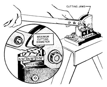
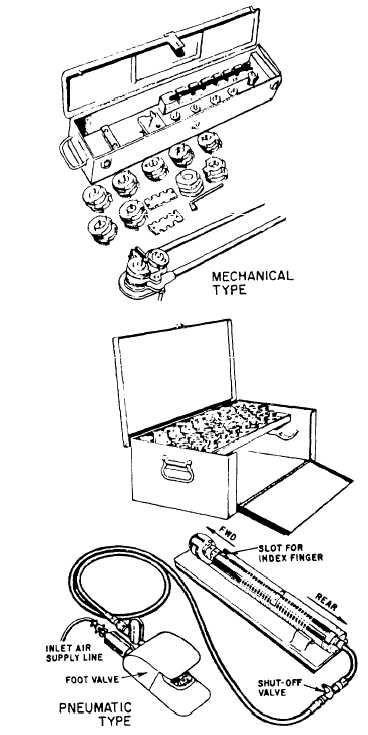
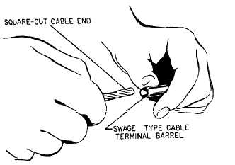
CABLE FABRICATION Control cables are fabricated mostly of extra flexible, preformed, corrosion-resistant steel. Control cables vary from 1/16 to 3/8 inch in diameter. Cables of 1/8 inch and larger are composed of 7 strands of 19 wires each. Cables 1/16 and 3/32 inch in diameter are composed of 7 strands of 7 wires each.Cable-Cutting Equipment Cutting cables may be accomplished by any convenient method except an oxyacetylene cutting torch. The method of cutting usually depends upon the tools and machines available. If a cable tends to unravel, the ends may be sweat soldered or wrapped with a strip of tape prior to cutting.Small diameter cable may be cut satisfactorily with a pair of heavy-duty diagonal cutters, side cutters, or a pair of wire nippers. Best results are obtained if the cutting jaws are held perpendicular to the cable during the cutting operation. Cables up to 3/32 of an inch in diameter may be cut in one operation by this method. Larger cables may require two or more cuts. When you cut large diameter cables, use the end of the cutting blade, and cut only a few strands at a time.The most satisfactory method of cutting cables is with a cable-cutting machine that has special jaws to accommodate various sizes of cable. See figure 9-28. To use this machine, position the cable in the proper diameter groove and hold the cable firmly within 2 inches of the cutting blades. Hold the cable at right angles to the cutting blades and pull the operating handle down sharply.A cold chisel and a soft metal block may also be used for cutting cables. This method should be used only as a last resort because of the way the cable ends will be frayed.Terminal Swaging After the cable is cut, the next step in making up an aircraft cable is attachment of the terminals. Most terminal fittings are SWAGED onto the ends of control system cables. Swaging is essentially a squeezing process in which the cable is inserted into the barrel of the terminal. Then pressure is applied by dies in a swaging machine to compress the barrel of the terminal tightly around the cable. The metal of the inside walls of the barrel is molded and cold flowed by force into the crevices of the cable. Figure 9-29 shows two types of hand-swaging tools. The one in the upper part of the illustration is mechanically operated, while the lower one is pneumatically operated. When you prepare to swage a terminal, cut the cable to the required length. Be sure to allow for the elongation (increase in length due to stretching) of the fitting that will occur during the swaging process. The amount of elongation will vary with the type and size of fitting used. Therefore, the elongation must be taken into account whenever you make up any cable. The Structural Hardware Manual, NAVAIR 01-1A-8, provides elongation data for all types and sizes of fittings.Make sure that the cable end is cut square and clean and that all strands remain in a compact group, as shown in figure 9-30. Place a drop or two of light lubricating oil on the cable end. Then, insert the end into the terminal to a depth of about 1 inch. Bend the cable toward the terminal, straighten it back to the normal position, and then push the cable all the way into the terminal barrel. This bending process puts a kink in the cable end to hold the terminal in place until the swaging operation is completed. It also tends to separate and spread the strands inside the terminal barrel and reduces the strain caused by swaging. Both of the hand-swaging tools shown in figure 9-29 are widely used by naval aircraft maintenance activities. The procedure for using both types is described in the following paragraphs.
Figure 9-29.Hand-swaging tools-mechanical and pneumatic.When operating the mechanical swaging tool, you should place the proper size pair of dies on the operation is performed. As the dies rotate, they pull of the tool, as shown in figure 9-31, and the swaging swaging tool. The terminal is then located in the jaws
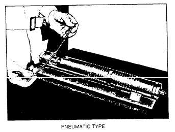
After completion of swaging and removal of the fitting from the swaging tool, measure the outside diameter of the shank with a micrometer or with the gauge furnished with the swaging outfit to determine whether or not the terminal has been swaged sufficiently. This may be determined by checking the measurement with the applicable cable terminal table in NAVAIR 01-1A-8. The pneumatic swaging tool shown in figure 9-29 is a lightweight portable unit designed to precision swage the metal of a terminal into the interstices (crevices) of the cable strands. The swager may be mounted on a baseplate and used on a bench, or it can be taken to the job. When the swaging tool is taken to the location of the job, it may be held in your hand or cradled in your arm. The pneumatic swaging kit has several different sizes and types of dies used for swaging ball-and-sleeve terminals and for cutting and trimming cable. Like the mechanical swaging tool, the dies come in matched sets and must be used together. The dies are installed by inserting either die through the yoke opening into the die cavity. The keyway should be down and the shank facing the rear of the swager. Slide the first die back in order to clear the opening for the insertion of the mating die. The second die is inserted with the shank facing forward. The following step-by-step procedures are recommended for setting up the pneumatic swaging tool : 1. Connect the air supply to the foot valve. For efficient operation, use an inlet air line with at least 3/8-inch inside diameter and a minimum of 90 pounds of line pressure. 2. Connect the swager air line to the foot valve. 3. Clean the dies, remove any steel particles that may have adhered to the die cavity, and apply a light film of oil to the entire die. 4. Insert the dies in the swaging tool as previously described. WARNING Do not insert or remove dies until the air supply that is connected to the swager is shut off. Failure to secure the air supply connected to the swager could result in personal injury to the operator.With the pneumatic tool set up for use, perform the following steps while swaging terminals to cables:1. Position the terminal on the cable, using the old cable as a pattern, or follow the instructions given in the applicable technical directives. When you are using a ball terminal, a minimum of 1 1/2 inches of cable must extend beyond the ball to allow room for holding and turning the terminal during swaging. The excess is trimmed, if necessary, after the swaging operation. When you use MS 20667 terminals, 1/4 inch of cable must extend through the terminal. On all other terminals, the cable is bottomed (inserted all of the way into the terminal).2. Each terminal is cleaned with a suitable solvent, and then coated with a light oil.3. With the terminals positioned in the cavity of the forward die, slide the rear die to its forward position using the slot provided in the yoke for the index finger.NOTE: To prevent damage to terminal or cable during the swaging cycle, maintain light pressure on the cable towards the front of the swager. This holds the terminal and cable firmly in the forward die cavity.4. Depress the foot valve firmly and rotate the cable back and forth in 180-degree arcs or complete revolutions. The length of time the foot valve is held depends upon the type and size of fitting being swaged. The proper time can be found by referring to the chart supplied with the pneumatic swaging tool. If the terminal will not rotate, stop swaging immediately; rotate the terminal 90 degrees, and start swaging again.5. Release the foot pedal to stop swaging, and remove the terminal from the swaging tool for inspection. If the diameter is oversize or the terminal surface is too rough, repeat the operation.If swaged terminals are to be used on both ends of the cable, recheck the overall length of the cable and trim it, if necessary, prior to installing the second terminal. Make certain that all additional fittings and accessories, such as cable stops and fairleads, are slipped onto the cable in the proper sequence. The other terminal may then be swaged, using the same procedures as used for the first one. |
 
|
|
|