Custom Search
|
|
  |
|
|
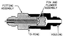
GAUGE AND PRESSURE TRANSMITTER SNUBBERS A gauge and pressure transmitter snubber is a hydraulic component located upstream of pressure gauges and pressure transmitters. Its purpose is to damper out system pressure surges that could cause possible damage to gauges and pressure transmitters. Snubbers also prevent cockpit hydraulic indicators from oscillating and fluctuating, which makes accurate reading of the gauge not only difficult but often impossible. Without the use of a snubber, pressure oscillations and other sudden pressure changes existing in hydraulic systems could affect the delicate internal mechanism of both gauges and transmitters. This may cause either complete destruction of the gauge or transmitter or, often worse, partial damage, resulting in false readings. The basic components of a snubber are the housing, fitting assembly with a fixed orifice diameter, and the pin and plunger assembly, as shown in figure 7-39. The snubbing action is obtained by metering fluid through the snubber. The fitting assembly orifice restricts the amount of fluid that flows to the gauge or pressure transmitter, thereby snubbing the force of a pressure surge. The pin is pushed and pulled through the orifice of the fitting assembly by the plunger, keeping it clear and at a uniform size.
According to the military specifications discussed earlier in this chapter, an aircraft may have a standby hydraulic system for emergency operation of the flight controls, a compressed air (pneumatic) system for operating the brakes, and a mechanically operated system for lowering the landing gear. Inspection and maintenance of these systems are also your responsibility. On aircraft using a standby hydraulic system, the emergency power system components will usually include a reservoir, a pump, and an emergency control in the cockpit for switching from NORMAL to EMERGENCY. Additional components will vary from aircraft to aircraft, depending on the method used for driving the emergency pump. The emergency system pump may be electric-motor driven, ram-air turbine driven, or it may be hand operated. All three methods are currently used on naval aircraft. Regardless of the method used in driving the pump, the emergency power system must be completely independent of the normal power system. The normal and emergency lines are usually separated as far apart from each other as practicable. This is done to reduce to a minimum the possibility of both lines being ruptured by a single projectile. The emergency reservoir is usually located as remotely as practicable from the normal reservoir, but it is generally possible to fill both reservoirs through a common filler port. Usually, the filler port is located on the normal system reservoir. |
 
|
|
|