Custom Search
|
|
  |
|
|
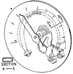
PRESSURE INDICATORS Pressure gauges installed in hydraulic and pneumatic systems are used to indicate existing hydraulic and pneumatic pressures, and are calibrated in pounds per square inch. Naval aircraft use both the direct reading gauges and the synchro (electric) type.Direct Reading Type Direct reading gauges are used in installations such as accumulators, emergency air bottles, arresting gear snubbers, and brake systems. The gauge is connected directly into units or lines leading from units and become part of the container or system. At these points the gauge is able to sample existing pressure.The main part of the direct reading gauge is the Bourdon tube. The Bourdon tube is a curved metal tube that is oval in cross-sectional shape (fig. 7-36).
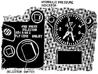
Assume that fluid pressure enters the Bourdon tube. Since fluid pressure will be transmitted equally in all directions and the area on the outside radius of the tube is greater than that of its inside, the force will also be greater on the outside radius, which tends to straighten the tube. As the movable end of the tube tries to turn outward, it turns the pivot segment gear. This gear meshes with a smaller rotary gear to which a pointer is attached, and its movement causes a reading on the pressure gauge. The gauge dial is calibrated so that the needle points to a number that corresponds to the exact pressure that is applied. When the pressure is removed, the Bourdon tube acts as a spring, and returns to its normal position. Synchro Type On most newer aircraft, an electrically operated (synchro) pressure indicator is used. Figure 7-37 shows the pressure indicator of a typical naval aircraft. This aircraft is equipped with three hydraulic systemsNo. 1 flight control system, No. 2 flight control system, and utility system. One indicator provides pressure indication for all three systems. This type of arrangement is desirable because it saves instrument panel space. The indicator system consists of three pressure transmitters, one located in each of the system lines,
Figure 7-37.Typical hydraulic pressure indicator. and a hydraulic pressure selector switch and dual pointer indicator, both located on the pilots instrument panel.The transmitters operate on the Bourdon tube principle. Expansion and contraction of the Bourdon tube is transmitted by mechanical linkage to the rotor of a transmitter synchro. The synchro transmits an electrical signal through wiring to the pressure indicator. The indicator contains two synchros mechanically attached to the two separate pointers. When the HYD PRESS SELECTOR switch (fig. 7-37) is in the No. 1 and No. 2 FLT CONT position, the pointers (marked "1" and "2") indicate the pressure in their respective systems, independent of each other. When the HYD PRESS SELECTOR switch is in the UTILITY position, the synchros are connected in electrical parallel, and the pointers align with each other and act as one.Although the Aviation Electricians Mate is responsible for inspecting and maintaining all the aircraft gauges and other instruments, you must know how to read the hydraulic pressure gauge to inspect and maintain the hydraulic system.Pressure gauges on some naval aircraft are calibrated to register from 0 to 2,000 psi; on others they register from 0 to 4,000 psi. The gauge in figure 7-37 is an example of the latter type. As shown in figure 7-37, on gauges designed for a range of 0 to 4,000 psi, the dial is calibrated with four major markings with the numerals 1,2,3, and 4. One major intermediate graduation between each numeral and four minor intermediate markings between the major markings are for reading to the
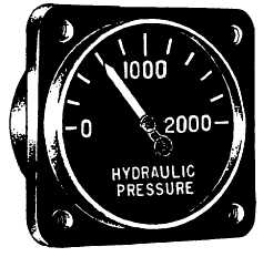
nearest 100 psi. On these gauges, the numeral reading must be multiplied by 1,000 to obtain the actual pressure in psi. On gauges designed for a range of 0 to 2,000 psi, the dial is calibrated with two major markings, the numerals 1,000 and 2,000, and four intermediate graduations for reading to the nearest 200 psi. A gauge of this type is shown in figure 7-38. |
 
|
|
|