Custom Search
|
|
  |
|
|
AIRCRAFT DRAWINGS Learning Objective: Recognize basic steps used in troubleshooting aircraft systems and various sources of information available.Much of the information contained in the various manuals issued by the Naval Air Systems Command for Navy aircraft and equipment is in the form of schematic, block, and pictorial drawings or diagrams. In order to understand how a system or component of the aircraft functions, you must be able to read and understand these drawings and diagrams.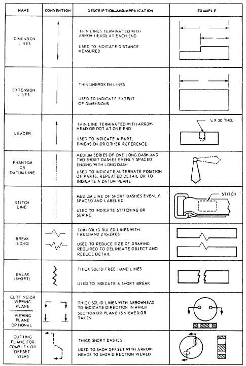 Figure 3-3.Line characteristics-Continued. MEANING OF LINES The alphabet of lines is the common language of the technician and the engineer. In drawing an object, a draftsman not only arranges the different views in a certain manner, but also uses different types of lines to convey information. Line characteristics such as width, breaks in the line, and zigzags have meanings, as shown in figure 3-3. INTERPRETATION OF DRAWINGS Schematic drawings are usually used to illustrate the various electrical circuits, hydraulic systems, fuel 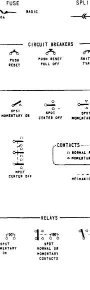   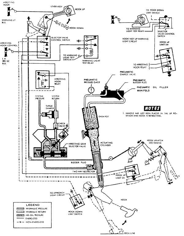 Figure 3-5.-Arresting gear system schematic. systems, and other systems of the aircraft. The components of an electrical circuit are normally represented by the standard electrical symbols shown in figure 3-4. Look at this figure and notice the electrical symbols for fuse, splice, ground, and polarity. Figure 3-5 is a schematic diagram that shows an arresting gear system. Different symbols in the legend indicate the flow of hydraulic fluid. The diagram also indicates energized and nonenergized wires. Each component is illustrated and identified by name. Arrows indicate the movement of each component.
Block diagrams may be used to illustrate a system. The nosewheel steering system in figure 3-6 is a good example of the use of a block diagram.In the block diagram, each of the components of the system is represented by a block. The name of the component represented by each block is near that block. Block diagrams are also useful in showing the relationship of the components. They also may show the sequence in which the different components operate.A pictorial drawing is a representation of both the detail and the entire assembly. Figure 3-7 is an example of a pictorial drawing. Another use of this type of drawing is to show disassembly, or an exploded view. This type of drawing enables the mechanic to see how the parts of a particular piece of equipment are put together.Orthographic drawings are used to show details of parts, components, and other objects, and are primarily used by the manufacturer of the object. Usually, two or more views of the object are given on the drawing. Detailed instructions on reading orthographic, as well as all other types of drawings, are contained in Reading and Sketching NAVEDTRA 10077-F1. |
|
|
|