Custom Search
|
|
  |
|
|
SUBSTITUTION AND INTERCHANGEABILITY
OF AIRCRAFT METALS In selecting interchangeable or substitute materials for the repair and maintenance of naval aircraft, it is important that you check the appropriate aeronautic technical publications when specified materials are not in stock or not obtainable from another source. It is impossible to determine if another material is as strong as the original by mere observation. There are four requirements that you must keep in mind in this selection. The first and most important of these is maintaining the original strength of the structure. The other three are maintaining contour or aerodynamic smoothness, maintaining original weight, if possible, or keeping added weight to a minimum, and maintaining the original corrosive-resistant properties of the metal. Because different manufacturers design structural members to meet various load requirements, you can appreciate the importance of checking the specific technical publication. Structural repair of these members, apparently similar in construction, will thus vary in their load-carrying design with different aircraft.Structural repair instructions, including tables of interchangeability and substitution for ferrous and nonferrous metals and their specifications for all types of aircraft used by the Navy, are normally prepared by the contractor. Such instructions are usually contained in the NA 01-XXX-3 manual covering structural repair instructions for specific models of aircraft. Similar information is also contained in Structural Repair, NA 01-1A-1.Aerospace Metals-General Data and Usage Factors, fabrication and repair. Always consult these publications and the NA 01-XXX-3 aircraft manual for the specific type of aircraft when confronted with a problem concerning maintenance and repair involving substitution and interchangeability of aircraft structural metals. Be sure you have the most recent issue of the aeronautic technical publication.HARDNESS TESTING Learning Objective: Recognize hardness testing methods, related equipments, and their operationHardness testing is a method of determining the results of heat treatment as well as the state of a metal prior to heat treatment. Since hardness values can be tied in with tensile strength values and, in part, with wear resistance, hardness tests are an invaluable check of heat-treatment control and of material properties. Practically all hardness testing equipments now in service use the resistance to penetration as a measure of hardness. Included among the better known bench-type hardness testers are the Brinell and the Rockwell, both of which are described and illustrated in this section. Also included are three portable type hardness testers now being used by maintenance activities.
Figure 1-25.-Brinell hardness tester.
Figure 1-26.-Microscopic view of impression. BRINELL TESTER The Brinell hardness tester, shown in figure 1-25, uses a hardened spherical ball, which is forced into the surface of the metal. The ball is 10 millimeters (0.3937
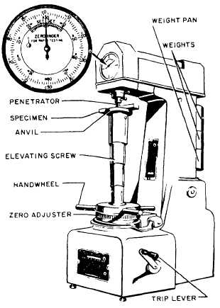
Figure 1-27.-Rockwell hardness tester. inch) in diameter. A pressure of 3,000 kilograms (6,600 pounds) is used for ferrous metals and 500 kilograms for nonferrous metals. Normally, the load should be applied for 30 seconds. In order to produce equilibrium, this period may be increased to 1 minute for extremely hard steels. The load is applied by means of hydraulic pressure. The hydraulic pressure is built up by a hand pump or an electric motor, depending on the model of tester. A pressure gauge indicates the amount of pressure. There is a release mechanism for relieving the pressure after the test has been made, and a calibrated microscope is provided for measuring the diameter of the impression in millimeters. The machine has various shaped anvils for supporting the specimen and an elevating screw for bringing the specimen in contact with the ball penetrator. There are attachments for special tests.To determine the Brinell hardness number for a metal, the diameter of the impression is first measured, using the calibrated microscope furnished with the tester. Figure 1-26 shows an impression as seen throughTable 1-3.-Portion of Conversion Table Furnished with Brinell Tester
the microscope. After measuring the diameter of the impression, the measurement is converted into the Brinell hardness number on the conversion table furnished with the tester. A portion of the conversion table is shown in table 1-3. |
|
|
|