 |
||
|
|
||
| |||||||||||||||
|
|
SPARK TEST The spark test is made by holding a sample of the material against an abrasive wheel. By visually inspecting the spark stream, an experienced metalworker can identify the metals with considerable accuracy. This test is fast, economical, convenient, and easily accomplished, and there is no requirement for special equipment. We can use this test for identifying metal salvaged from scrap. Identification of scrap is particularly important when selecting material for cast iron or cast steel heat treatment. When you hold a piece of iron or steel in contact with a high-speed abrasive wheel, small particles of the metal are torn loose so rapidly that they become red-hot. As these glowing bits of metal leave the wheel, they follow a path (trajectory) called the carrier line. This carrier line is easily followed with the eye, especial] y when observed against a dark background. The sparks given off, or the lack of sparks, aid in the identification of the metal. The length of the spark stream, the color, and the form of the sparks are features you should look for. Figure 1-2 illustrates the terms used in referring to various basic spark forms produced in spark testing. Steels having the same carbon content but differing alloying elements are difficult to identify because the alloying elements affect the carrier lines, the bursts, or the forms of characteristic bursts in the spark picture, The effect of the alloying element may slow or accelerate the carbon spark or make the carrier line lighter or darker in color. Molybdenum, for example, appears as a detached, orange-colored spearhead on the end of the carrier line. Nickel appears to suppress the effect of the carbon burst; however, the nickel spark can be identified by tiny blocks of brilliant white light. Silicon suppresses the carbon burst even more than nickel. When silicon is present, the carrier line usually ends abruptly in a white flash of light. Spark testing may be done with either a portable or stationary grinder. In either case, the speed on the outer rim of the wheel should not be less than 4,500 feet per minute. The abrasive wheel should be rather coarse, very hard, and kept clean to produce a true spark To conduct a spark test on an abrasive wheel, hold the piece of metal on the wheel in a position that allows the spark stream to cross your line of vision. By trial and error, you soon discover what pressure is needed to get a stream of the proper length without reducing the speed of the grinder. Excessive pressure increases the temperature of the spark stream. This, in turn, increases the temperature of the burst and gives the appearance of a higher carbon content than actually is present. When making the test, watch a point about one third of the distance from the tail end of the spark stream. Watch only those sparks that cross your line of vision and try to forma mental image of the individual spark. Fix this spark image in your mind and then examine the whole spark picture. While on the subject of abrasive wheels, it is a good idea to discuss some of the safety precautions associated with this tool. 0 Never use an abrasive wheel that is cracked or out of balance because the vibration causes the wheel to shatter. When an abrasive wheel shatters, it can be disastrous for personnel standing in line with the wheel. Always check the wheel for secure mounting and cracks before putting it to use. When you install a new wheel on a grinder, be sure that it is the correct size. Remember, as you increase the wheel radius, the peripheral speed at the rim also increases, even though the driving motor rpm remains the same. Thus, if you should use an oversized wheel, there is a distinct danger the peripheral speed (and consequent centrifugal force) can become so great that the wheel may fly apart. Use wheels that are designed for a specific rpm. Guards are placed on grinders as protection in case a wheel should shatter. 0 Never use a grinder when the guards have been removed. When turning the grinder on, you should stand to one side. This places you out of line with the wheel in case the wheel should burst. 9 Never overload a grinder or put sideways pressure against the wheel, unless it is expressly built to withstand such use. 0 Always wear appropriate safety goggles or a face shield while using the grinder. Ensure that the tool rest (the device that helps the operator hold the work) is adjusted to the minimum clearance for the wheel. Move the work across the entire face of the wheel to eliminate grooving and to minimize wheel dressing. Doing this prolongs the life of the wheel. 0 Keep your fingers clear of the abrasive surface, and do not allow rags or clothing to become entangled in the wheel. * Do not wear gloves while using an abrasive wheel. Never hold metal with tongs while grinding. 0 Never grind nonferrous metals on a wheel intended for ferrous metals because such misuse clogs the pores of the abrasive material. This buildup of metal may cause it to become unbalanced and fly apart. Grinding wheels require frequent reconditioning. Dressing is the term used to describe the process of cleaning the periphery. This cleaning breaks away dull abrasive grains and smooths the surface, removing all the grooves. The wheel dresser shown in figure 1-3 is used for dressing grinding wheels on bench and pedestal grinders. For more information on grinding wheels, you should consult chapter 5 of NAVEDTRA 10085-B2 (Tools and Their Uses). Referring now to figure 1-4, notice that in lowcarbon steel (view A), the spark stream is about 70 inches long and the volume is moderately large. In high-carbon steel (view B), the stream is shorter (about 55 inches) and the volume larger. The few sparklers that may occur at any place in low-carbon steel are forked,
Figure 1-3.-Using a grinding wheel dresser.
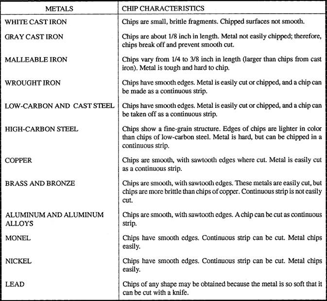
Figure 1-4.-Spark patterns formed by common metals. Table 1-4.-Metal Identification by Chip Test
and in high-carbon steel, they are small and repeating. Both metals produce a spark stream white in color. Gray cast iron (view C) produces a stream of sparks about 25 inches in length. The sparklers are small and repeating, and their volume is rather small. Part of the stream near the wheel is red, and the outer portion is straw-colored. Monel and nickel (view D) form almost identical spark streams. The sparks are small in volume and orange in color. The sparks form wavy streaks with no sparklers. Because of the similarity of the spark picture, these metals must be distinguished from each other by some other method. Stainless steel (view E) produces a spark stream about 50 inches in length, moderate volume, and with few sparklers. The sparklers are forked. The stream next to the wheel is straw-colored, and at the end, it is white. The wrought-iron spark test (view F) produces a spark stream about 65 inches in length. The stream has a large volume with few sparklers. The sparks appear near the end of the stream and are forked. The stream next to the wheel is straw-colored, and the outer end of the stream is a brighter red. One way to become proficient in spark testing ferrous metals is to gather an assortment of samples of known metals and test them. Make all of the samples about the same size and shape so their identities are not revealed simply by the size or shape. Number each sample and prepare a list of names and corresponding numbers. Then, without looking at the number of the sample, spark test one sample at a time, calling out its name to someone assigned to check it against the names and numbers on the list. Repeating this process gives you some of the experience you need to become proficient in identifying individual samples. CHIP TEST Another simple test used to identify an unknown piece of metal is the chip test. The chip testis made by removing a small amount of material from the test piece with a sharp, cold chisel. The material removed varies from small, broken fragments to a continuous strip. The chip may have smooth, sharp edges; it maybe coarsegrained or fine-grained; or it may have sawlike edges. The size of the chip is important in identifying the metal. The ease with which the chipping can be accomplished should also be considered. The information given in table 1-4 can help you identify various metals by the chip test. MAGNETIC TEST The use of a magnet is another method used to aid in the general identification of metals. Remember that ferrous metals, being iron-based alloys, normally are magnetic, and nonferrous metals are nonmagnetic. This test is not 100-percent accurate because some stainless steels are nonmagnetic. In this instance, there is no substitute for experience. |
|
Privacy Statement - Press Release - Copyright Information. - Contact Us - Support Integrated Publishing |