| Tweet |

Custom Search
|
|
 
|
||
|
ASSEMBLY OF THE RIFLE To assemble the rifle, reverse the procedures of disassembly. 1. Insert the end of the assembly spring into the lower receiver extension; depress the cocked hammer to allow passage of the buffer assembly; depress the buffer retainer with the nose of a cartridge or the tip of the firing pin; seat the buffer assembly; and then release the buffer retainer. 2. Assemble the bolt carrier group by grasping the bolt and the extractor with the action spring. Seat the extractor in the extractor recess; apply pressure on the extractor to align the pinhole; and then insert the extractor pin. Pickup the bolt carrier with the carrier key up and to the front; insert the bolt into the front of the bolt carrier, ensuring that the ejector is down and to the left. Replace the cam pin into its well, and rotate the cam pin 90 degrees (one-quarter turn) to align the holes for the firing pin in the bolt and the cam pin. Grasp the lugged rim of the bolt, and turn it until the cam pin is directly under the bolt carrier key. Insert the firing pin through the open end of the bolt carrier and seat it folly. Insert the firing pin retaining pin (if you encounter resistance, rotate the pin while inserting it). CAUTION Do NOT attempt to spread the slotted end of the firing pin retaining pin. Check for proper assembly by elevating the front of the bolt. If the firing pin drops out, the firing pin retaining pin is not between the front and rear spool. The bolt carrier group is improperly assembled. 3. Grasp the upper receiver with the carrying handle up. Place the charging handle into the groove in the top of the upper receiver. The lugs on the charging handle must be seated in their grooves in the receiver. Place the bolt carrier group into the open end of the receiver, ensuring that the bolt carrier key is in the slot
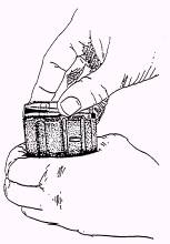
Figure 3-20.-The M16A1 service rifle field-stripped. on the underside of the charging handle and the bolt is forward in the unlock position. Push forward on the bolt carrier group and charging handle until it is fully seated. 4. Place the upper receiver group and lower receiver group together, and reseat the receiver pivot pin. 5. With the hammer cocked and the selector lever on SAFE, close the weapon and seat the takedown pin. 6. Replace the handguards, and be sure that the slip ring is fully seated on the lower lip of both sections of the handguards. Take care to prevent damage to the upper and lower lips and to ensure proper seating. 7. A complete fictional check of the rifle consists of checking the operation of the weapon while the selector is in the SAFE, SEMI, and AUTO positions. Use the following sequence for a rapid, complete check. You may use any portion of the check alone to determine the operational condition of any specific fire selection. NOTE: Disengage the takedown pin and open receivers. The hammer must be in the cocked position. a. SAFE position. Pull the trigger; the hammer should not fall. b. SEMI position. Pull the trigger; the hammer should fall. Hold the trigger to the rear, recock the hammer, and release the trigger. The hammer should transfer from hammer hooks and disconnect to the hammer and sear engagement. c. AUTO position. Pull the trigger; the hammer should fall. Hold the trigger to the rear, and recock the hammer. The hammer is now under the automatic sear. Still holding the trigger to the rear, push forward on the automatic sear. The hammer should frill. Still holding the trigger to the rear, recock the hammer, release the trigger, and push forward on the automatic sear. The hammer should transfer to the sear engagement. Move the selector lever to SAFE or SEMI position. Close the receivers and engage the takedown pin. CAUTION If the selector lever is not moved to the SAFE or SEMI position before you close the receivers, you can damage the automatic sear. d. SEMI position. Pull the charging handle to the rear. Make certain the chamber is clear; then release the charging handle. Pull the trigger. The hammer should fall. Figure 3-21.-Loading cartridges into the magazine, 20 rounds capacity. |
 |
|
|
||