Custom Search
|
|
  |
|
|
Figure 3-18C. - SCR structure.
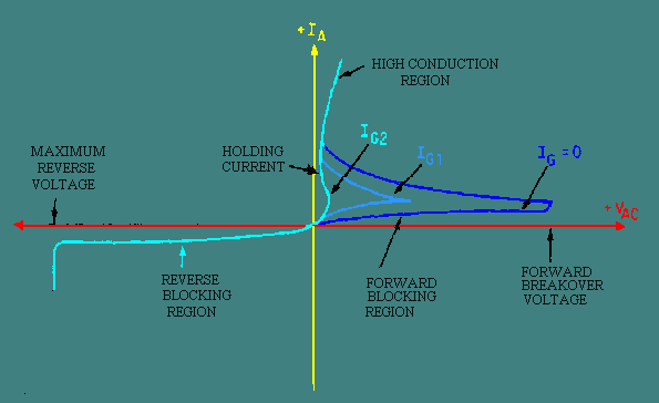
In operation the collector of Q2 drives the base of Q1, while the collector of Q1 feeds back to the base of Q2. (Beta) 1 is the current gain of Q1, and (Beta ) 2 is the current gain of Q2. The gain of this positive feedback loop is their product, 1 times 2. When the product is less than one, the circuit is stable; if the product is greater than unity, the circuit is regenerative. A small negative current applied to terminal G will bias the NPN transistor into cutoff, and the loop gain is less than unity. Under these conditions, the only current that can exist between output terminals A and C is the very small cutoff collector current of the two transistors. For this reason the impedance between A and C is very high. When a positive current is applied to terminal G, transistor Q2 is biased into conduction, causing its collector current to rise. Since the current gain of Q2 increases with increased collector current, a point (called the breakover point) is reached where the loop gain equals unity and the circuit becomes regenerative. At this point, collector current of the two transistors rapidly increases to a value limited only by the external circuit. Both transistors are driven into saturation, and the impedance between A and C is very low. The positive current applied to terminal G, which served to trigger the self-regenerative action, is no longer required since the collector of PNP transistor Q1 now supplies more than enough current to drive Q2. The circuit will remain on until it is turned off by a reduction in the collector current to a value below that necessary to maintain conduction. The characteristic curve for the SCR is shown in figure 3-19. With no gate current, the leakage current remains very small as the forward voltage from cathode to anode is increased until the breakdown point is reached. Here the center junction breaks down, the SCR begins to conduct heavily, and the drop across the SCR becomes very low. Figure 3-19. - Characteristic curve for an SCR.
The effect of a gate signal on the firing of an SCR is shown in figure 3-20. Breakdown of the center junction can be achieved at speeds approaching a microsecond by applying an appropriate signal to the gate lead, while holding the anode voltage constant. After breakdown, the voltage across the device is so low that the current through it from cathode to anode is essentially determined by the load it is feeding. Figure 3-20. - SCR characteristic curve with various gate signals.
The important thing to remember is that a small current from gate to cathode can fire or trigger the SCR, changing it from practically an open circuit to a short circuit. The only way to change it back again (to commutate it) is to reduce the load current to a value less than the minimum forward-bias current. Gate current is required only until the anode current has completely built up to a point sufficient to sustain conduction (about 5 microseconds in resistive-load circuits). After conduction from cathode to anode begins, removing the gate current has no effect. The basic operation of the SCR can be compared to that of the thyratron. The thyratron is an electron tube, normally gas filled, that uses a filament or a heater. The SCR and the thyratron function in a very similar manner. Figure 3-21 shows the schematic of each with the corresponding elements labeled. In both types of devices, control by the input signal is lost after they are triggered. The control grid (thyratron) and the gate (SCR) have no further effect on the magnitude of the load current after conduction begins. The load current can be interrupted by one or more of three methods: (1) the load circuit must be opened by a switch, (2) the plate (anode) voltage must be reduced below the ionizing potential of the gas (thyratron), (3) the forward-bias current must be reduced below a minimum value required to sustain conduction (SCR). The input resistance of the SCR is relatively low (approximately 100 ohms) and requires a current for triggering; the input resistance of the thyratron is exceptionally high, and requires a voltage input to the grid for triggering action. Figure 3-21. - Comparison of an SCR and a thyratron.
The applications of the SCR as a rectifier are many. In fact, its many applications as a rectifier give this semiconductor device its name. When alternating current is applied to a rectifier, only the positive or negative halves of the sine wave flow through. All of each positive or negative half cycle appears in the output. When an SCR is used, however, the controlled rectifier may be turned on at any time during the half cycle, thus controlling the amount of dc power available from zero to maximum, as shown in figure 3-22. Since the output is actually dc pulses, suitable filtering can be added if continuous direct current is needed. Thus any dc operated device can have controlled amounts of power applied to it. Notice that the SCR must be turned on at the desired time for each cycle. Figure 3-22. - SCR gate control signals.
When an ac power source is used, the SCR is turned off automatically, since current and voltage drop to zero every half cycle. By using one SCR on positive alternations and one on negative, full-wave rectification can be accomplished, and control is obtained over the entire sine wave. The SCR serves in this application just as its name implies - as a controlled rectifier of ac voltage. Q.14 The SCR is primarily used for what function? |
 |
|
|
Integrated Publishing, Inc. - A (SDVOSB) Service Disabled Veteran Owned Small Business
|