Custom Search
|
|
  |
|
|
Figure 3-4. - Schematic symbols of switches.
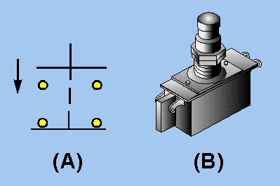
Single-Break and Double-Break Switches Switches can also be classified as SINGLE-BREAK or DOUBLE-BREAK switches. This refers to the number of places in which the switch opens or breaks the circuit. All of the switches shown so far have been single-break switches. A double-break switch is shown in figure 3-5. The schematic symbol shown in figure 3-5(A) shows that this switch breaks the circuit in two places (at both terminals). The upper part of the schematic symbol indicates that these contacts are in the open position and the circuit will close when the switch is acted upon (manually or automatically). The lower symbol shows closed contacts. These contacts will open the circuit when the switch is acted upon.
Figure 3-5. - Double-break pushbutton switch.
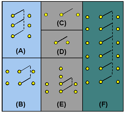
Figure 3-5(B) is a picture of the switch. This switch is called a pushbutton switch because it has a button that must be pushed to change the switch contact connections. Notice that the switch has four terminals. The schematic symbol in figure 3-5(A) shows that when one set of contacts is open, the other set of contacts is closed. This switch is a double-pole, single-throw, double-break switch. The number of poles in a switch is independent of the number of throws and whether it is a single or double break switch. The number of throws in a switch is independent of the number of poles and whether it is a single or double break switch. In other words, each characteristic of a switch (poles, throws, break) is not determined by either of the other characteristics. Figure 3-6 shows the schematic symbols for several different switch configurations. Figure 3-6. - Schematic symbols of switch configurations.
Rotary Switches A rotary switch is a midcontact switch part of the schematic with the contacts arranged in a full or partial circle. Instead of a pushbutton or toggle, the mechanism used to select the contact moves in a circular motion and must be turned. Rotary switches can be manual or automatic switches. An automobile distributor, the ignition switch on a motor vehicle, and the channel selector on some television sets are rotary switches. The automobile distributor cap and rotor are an example of the simplest form of an automatic rotary switch. Figure 3-7shows a portion of an automobile ignition system with the distributor cap and rotor shown. The rotor is the portion of this switch that moves (rotates) and selects the circuit (spark plug). The rotor does not actually touch the contacts going to the spark plugs, but the signal (spark) jumps the gap between the rotor and the contacts. This switch has one input (the rotor) and six positions (one for each spark plug). The schematic diagram for this rotary switch is shown below the illustration of the distributor cap. |
 |