Custom Search
|
|
  |
|
|
CAPACITORS IN SERIES AND PARALLEL
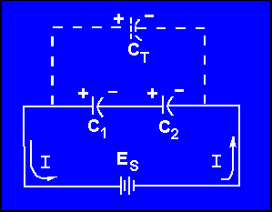
Capacitors may be connected in series or in parallel to obtain a resultant value which may be either the sum of the individual values (in parallel) or a value less than that of the smallest capacitance (in series). CAPACITORS IN SERIES The overall effect of connecting capacitors in series is to move the plates of the capacitors further apart. This is shown in figure 3-13. Notice that the junction between C1 and C2 has both a negative and a positive charge. This causes the junction to be essentially neutral. The total capacitance of the circuit is developed between the left plate of C1 and the right plate of C2. Because these plates are farther apart, the total value of the capacitance in the circuit is decreased. Solving for the total capacitance (CT) of capacitors connected in series is similar to solving for the total resistance(RT)of resistors connected in parallel. Figure 3-13. - Capacitors in series.
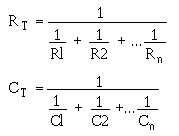
Note the similarity between the formulas for RT and CT:
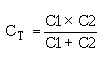
If the circuit contains more than two capacitors, use the above formula. If the circuit contains only two capacitors, use the below formula:
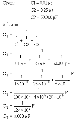
Note: All values for CT, C1, C2, C3,... C n should be in farads. It should be evident from the above formulas that the total capacitance of capacitors in series is less than the capacitance of any of the individual capacitors. Example: Determine the total capacitance of a series circuit containing three capacitors whose values are 0.01 mF, 0.25 mF, and 50,000 pF, respectively.
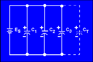
The total capacitance of 0.008mF is slightly smaller than the smallest capacitor (0.01mF). When capacitors are connected in parallel, one plate of each capacitor is connected directly to one terminal of the source, while the other plate of each capacitor is connected to the other terminal of the source. Figure 3-14 shows all the negative plates of the capacitors connected together, and all the positive plates connected together. C T, therefore, appears as a capacitor with a plate area equal to the sum of all the individual plate areas. As previously mentioned, capacitance is a direct function of plate area. Connecting capacitors in parallel effectively increases plate area and thereby increases total capacitance. Figure 3-14. - Parallel capacitive circuit.
For capacitors connected in parallel the total capacitance is the sum of all the individual capacitances. The total capacitance of the circuit may by calculated using the formula:
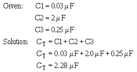
where all capacitances are in the same units. Example: Determine the total capacitance in a parallel capacitive circuit containing three capacitors whose values are 0.03 mF, 2.0 mF, and 0.25 mF, respectively.
Q.16 What is the total capacitance of a circuit that contains two capacitors (10 mF and 0.1 mF) wired together in series? |
 |