Custom Search
|
|
  |
|
|
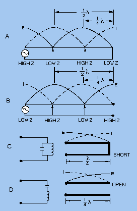
TERMINATING A TRANSMISSION LINE A transmission line is either NONRESONANT or RESONANT. First, let us define the terms nonresonant lines and resonant lines. A nonresonant line is a line that has no standing waves of current and voltage. A resonant line is a line that has standing waves of current and voltage. Nonresonant Lines A nonresonant line is either infinitely long or terminated in its characteristic impedance. Since no reflections occur, all the energy traveling down the line is absorbed by the load which terminates the line. Since no standing waves are present, this type of line is sometimes spoken of as a FLAT line. In addition, because the load impedance of such a line is equal to Z0, no special tuning devices are required to effect a maximum power transfer; hence, the line is also called an UNTUNED line. Resonant Lines A resonant line has a finite length and is not terminated in its characteristic impedance. Therefore reflections of energy do occur. The load impedance is different from the Z0 of the line; therefore, the input impedance may not be purely resistive but may have reactive components. Tuning devices are used to eliminate the reactance and to bring about maximum power transfer from the source to the line. Therefore, a resonant line is sometimes called a TUNED line. The line also may be used for a resonant or tuned circuit. A resonant line is sometimes said to be resonant at an applied frequency. This means that at one frequency the line acts as a resonant circuit. It may act either as a high-resistive circuit (parallel resonant) or as a low-resistive circuit (series resonant). The line may be made to act in this manner by either open- or short-circuiting it at the output end and cutting it to some multiple of a quarter-wavelength. At the points of voltage maxima and minima on a short-circuited or open-circuited line, the line impedance is resistive. On a short-circuited line, each point at an odd number of quarter-wavelengths from the receiving end has a high impedance (figure 3-31, view A). If the frequency of the applied voltage to the line is varied, this impedance decreases as the effective length of the line changes. This variation is exactly the same as the change in the impedance of a parallel-resonant circuit when the applied frequency is varied. Figure 3-31. - Sending-end impedance of various lengths and terminations.
At all even numbered quarter-wavelength points from the short circuit, the impedance is extremely low. When the frequency of the voltage applied to the line is varied, the impedance at these points increases just as the impedance of a series-resonant circuit varies when the frequency applied to it is changed. The same is true for an open-ended line (figure 3-31, view B) except that the points of high and low impedance are reversed. At this point let us review some of the characteristics of resonant circuits so we can see how resonant line sections may be used in place of LC circuits. A PARALLEL-RESONANT circuit has the following characteristics:
A SERIES-RESONANT circuit has these characteristics:
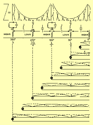
Since the impedance a generator sees at the quarter-wave point in a shorted line is that of a parallel-resonant circuit, a shorted quarter-wave- length of line may be used as a parallel-resonant circuit (figure 3-31, view C). An open quarter-wavelength of line may be used as a series-resonant circuit (view D). The Q of such a resonant line is much greater than can be obtained with lumped capacitance and inductance. Impedance for Various Lengths of Open Lines In figure 3-32, the impedance (Z) the generator sees for various lengths of line is shown at the top. The curves above the letters of various heights show the relative value of the impedances presented to the generator for the various line lengths. The circuit symbols indicate the equivalent electrical circuits for the transmission lines at each particular length. The standing waves of voltage and current are shown on each length of line. Figure 3-32. - Voltage, current, and impedance on open line.
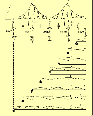
At all odd quarter-wave points (1/4 l, 3/4l, etc.), the voltage is minimum, the current is maximum, and the impedance is minimum. Thus, at all odd quarter-wave points, the open-ended transmission line acts as a series-resonant circuit. The impedance is equivalent to a very low resistance, prevented from being zero only by small circuit losses.At all even quarter-wave points (1/2 l, 1l, 3/2l, etc.), the voltage is maximum, the current is minimum, and the impedance is maximum. Comparison of the line with an LC resonant circuit shows that at an even number of quarter-wavelengths, an open line acts as a parallel-resonant circuit. The impedance is therefore an extremely high resistance.In addition, resonant open lines may also act as nearly pure capacitances or inductances. The illustration shows that an open line less than a quarter-wavelength long acts as a capacitance. Also, it acts as an inductance from 1/4 to 1/2 wavelength, as a capacitance from 1/2 to 3/4 wavelength, and as an inductance from 3/4 to 1 wavelength, etc. A number of open transmission lines, with their equivalent circuits, are shown in the illustration. Impedance of Various Lengths of Shorted Lines Follow figure 3-33 as we study the shorted line. At the odd quarter-wavelength points, the voltage is high, the current is low, and the impedance is high. Since these conditions are similar to those found in a parallel-resonant circuit, the shorted transmission line acts as a parallel-resonant circuit at these lengths. Figure 3-33. - Voltage, current, and impedance on shorted line.
At the even quarter-wave points voltage is minimum, current is maximum, and impedance is minimum. Since these characteristics are similar to those of a series-resonant LC circuit, a shorted transmission line whose length is an even number of quarter-wavelengths acts as a series-resonant circuit. Resonant shorted lines, like open-end lines, also may act as pure capacitances or inductances. The illustration shows that a shorted line less than 1/4 wavelength long acts as an inductance. A shorted line with a length of from 1/4 to 1/2 wavelength acts as a capacitance. From 1/2 to 3/4 wavelength, the line acts as an inductance; and from 3/4 to 1 wavelength, it acts as a capacitance, and so on. The equivalent circuits of shorted lines of various lengths are shown in the illustration. Thus, properly chosen line segments may be used as parallel-resonant, series-resonant, inductive, or capacitive circuits. |
 |