Custom Search
|
|
 
|
||
|
Changing Speed Most hydraulic equipment is driven by a 440-volt ac constant speed electric motor. These motors have to spin at very high speeds to be efficient. To be usable for driving a hydraulic pump or anything else, you must reduce the output speed of the motor. This is accomplished through reduction gears. The reduction gears are located in an oil-filled encasement, which normally appears to be part of the drive motor housing. Figure 4-6 will help you understand how this is possible. Wheel A has 10 teeth that mesh with the 40
Figure 4-6.-Simple reduction gears. teeth on wheel B. Wheel A will have to rotate four times to cause wheel B to make one rotation. Wheel C is fixed rigidly to the same shaft as wheel B. Therefore, wheel C makes the same number of revolutions as wheel B. However, wheel C has 20 teeth and meshes with wheel D that has 10 teeth. This causes wheel D to rotate twice for every one revolution of wheel C. If you rotate wheeI A at a speed of four revolutions per second, wheel B will rotate one revolution per second. Wheel C also moves one revolution per second, turning wheel D at a speed of two revolutions per second. You get an output speed of two revolutions per second from an input of four revolutions per second with a speed reduction of one half. Almost any increase or decrease in speed can be obtained by choosing the correct gears for the job. Magnifying Force Gear trains can be used to increase mechanical advantage. The rule is: whenever you reduce speed with a gear train, you increase the effect of the force applied. The theory of this principle will not be discussed here. For further information on gears and gear trains, as well as the theories of how they work, see the Navy training manual Basic Machines, NAVEDTRA 12199. LEVERS AND LINKAGES One of the simplest and most familiar types of machines is the lever. Levers are used to overcome big
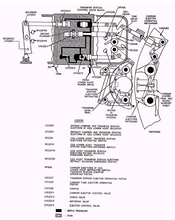
Figure 4-7.-A simple lever. resistances with relatively small effort. The principle of leverage is used extensive y throughout ordnance equipment. The three basic components that comprise all levers are the fulcrum (F), a force or effort (E), and a resistance (R). Look at the lever in figure 4-7. You seethe pivot point (F, fulcrum), the effort (E) that you apply at a distance (A) from the fulcrum, and a resistance (R) that acts at a distance (a) from the fulcrum. Distances (A) and (a) are the lever arms. The application of leverage in ordnance equipment uses mechanical linkages to transmit and increase force. Figure 4-8 shows the mechanical linkages in a 5"'/54Mk 42 Mod 10 carrier ejector assembly. The linkages act together to eject a complete round of ammunition from the transfer station to the carrier tube. The carrier tube must be completely open before the round is ejected into it. Therefore, a time delay slot is incorporated to allow the linkages to move, opening the carrier before the transfer station ejectors actuate. For further information on the fundamentals of levers and linkages, see the Navy training manual Basic Machines, NAVEDTRA 12199. In a broad sense, the term coupling applies to any device that holds two parts together. For our purposes, these two parts will normally be rotating shafts. In its most familiar application, a coupling will permit one shaft to transmit motion to another shaft that is, or may be, misaligned. The misalignment may be intentional, as in the case of an automobile drive shaft. The drive shaft links the output shaft of the transmission in the front of the automobile to the input shaft of the rear drive unit. The engine and transmission are fixed to the chassis, while the rear drive unit is spring-mounted to the chassis to ride over bumps in the road. The couplings (in this case, universal joints) allow for the efficient transmission of motion while at the same time providing flexibility in the drive train. The misalignment may also be unintentional or unavoidable
Figure 4-8.-The 5"/54 carrier ejector mechanism.
Figure 4-9.-Couplings and their applications. 4-6 because of wear or slippage. Figure 4-9 shows four types of couplings commonly used in ordnance equipment. The adjustable flexible coupling (also called vernier coupling) joins two shafts by means of a flexible metal disk with an adjustable element. By loosening the clamping bolt and turning the worm, you can turn the right-hand shaft. This type of coupling can be found on nearly all types of guns in applications that require finely adjusted mechanical outputs. A flexible coupling is similar to this but does not contain the adjustment feature. The fixed sliding lug (Oldham) coupling is not as rigid as its name implies. While it is not designed to connect shafts that meet at an angle, it will transmit motion and allow for some misalignment between shafts that are parallel but fail to meet each other exactly. Figure 4-9 shows the output shaft of a drive motor linked by a fixed sliding lug to the input shaft of a hydraulic pump located inside a fluid reservoir. This is necessary for two reasons. First, if the shaft were common to the two devices, when one device required replacement, both would have to be replaced. Second, any wear or misalignment in one device would cause bearing or seal wear in the other device. The universal joint is used in ordnance equipment, as we said earlier, where the shafts intentionally meet at an angle. Universal joints also have the advantage of great strength, making them useful in heavy load applications. Other connecting devices and adjustments are discussed in chapter 12 under mechanical adjustments. |
 |
|
|
||