Custom Search
|
|
 
|
||
|
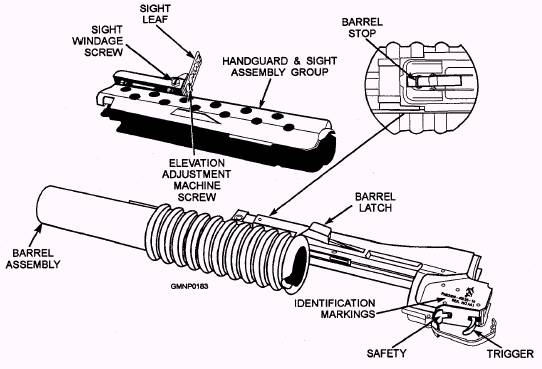
Receiver Assembly The receiver assembly (fig. 3-109) consists of an aluminum receiver that houses the barrel latch, the barrel stop, and the firing mechanism. The receiver assembly attaches to the barrel of the rifle, mounting the grenade launcher to the rifle. The receiver assembly also contains the follower assembly, the trigger, and the safety components that serve to fire or prevent accidental firing of the grenade launcher. The safety is just forward of the trigger, inside the trigger guard. The safety must be in the forward position (fig. 3-109) to fire the launcher. The safety must be in the most rearward position to place the launcher on safe. The safety must be placed manually in either of these positions. The barrel latch, when depressed, unlocks the barrel so that it can be moved forward along the receiver assembly. As the barrel and barrel extension (which are interlocked with the cocking lever) move forward, the cocking lever is forced downward. The cocking lever, in turn, forces the spring-loaded tiring pin rearward. At the same time, the spring-loaded follower follows the barrel extension forward. As the barrel continues its
Figure 3-109.-40-mm grenade launcher, M203, controls and their identifications. forward movement, the barrel extension disengages from the cocking lever. The movement of the follower is restricted by the receiver; the follower holds the cocking lever in the DOWN position. When the barrel is moved rearward, the follower is driven rearward, the cocking lever again engages the barrel extension, and the firing pin moves slightly forward and engages the sear. The barrel stop (fig. 3-109) limits the forward motion of the barrel assembly. This prevents the barrel assembly from sliding off the receiver assembly barrel track during loading and cocking operations. When the barrel stop is depressed, it allows the barrel assembly to be removed from the receiver assembly for maintenance. Quadrant Sight Assembly The M203 has a quadrant sight assembly (fig. 3-110), which connects to the carrying handle of the M16 rifle. It consists of a sight arm, a range selection quadrant, and mounting brackets. The sight arm contains an aperture and post for sighting operations of the launcher. The range selection quadrant has embossed range graduations from 50 to 400 in 25-meter increments. The quadrant sight is used at ranges in excess of the 250 meters that is covered by the leaf sight. The 25-meter increments also allow for better accuracy at a greater number of range variations than the leaf sight. Barrel Assembly The barrel (refer to fig. 3-109) of the barrel assembly is constructed of specially treated and machined aluminum. The barrel extension is a rectangular, chrome-plated steel bar. It attaches to the barrel and provides a means of attaching the barrel to the receiver assembly. The handgrip is a molded plastic corrugated sleeve. When the grenade launcher is being fired, the plastic handgrip allows the Operator to hold the launcher without any discomfort from the heat. |
 |
|
|
||