Custom Search
|
|
 
|
||
|
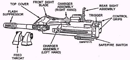
MK 19 MOD 3 MACHINE GUN The Mk 19 Mod 3 machine gun (fig. 3-101) fires a 40-mm grenade with antipersonnel fragmentation and
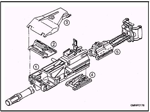
Figure 3-101.-Mk 19 Mod 3 machine gun. 3-50 light armor-piercing capability. It is an air-cooled, belt-fed, blowback-operated, fully automatic weapon. The Mk 19 Mod 3 machine gun is found on riverine craft and surface vessels that are tasked to operate in confined waters, such as the Persian Gulf. Major Components The Mk 19 Mod 3 machine gun has five major components, as shown in figure 3-102. These are the receiver assembly, the feed slide assembly and tray, the top cover assembly, the sear assembly, and the bolt and backplate assembly. RECEIVER ASSEMBLY.- The receiver assembly (fig. 3-102, 1) provides support for the other major assemblies of the weapon. FEED SLIDE ASSEMBLY AND TRAY.- The feed slide assembly and tray (fig. 3-102, 2) holds the rounds in the feeder and indexes ammunition into the firing position. TOP COVER ASSEMBLY.- The top cover assembly (fig. 3-102, 3) holds the feed slide assembly and tray. It is opened by a latch (left side) for loading or to clean and inspect the weapon. SEAR ASSEMBLY.- The sear assembly (fig.3-102, 4) holds the receiver sear. Trigger action depresses the sear, releasing the bolt and allowing the bolt to move forward for firing. The safety is attached to the sear assembly. When the safety slide is activated, it blocks the sear from being depressed by the operator as long as the safety is on S (SAFE). BOLT AND BACKPLATE ASSEMBLY.- Located on the bolt and backplate assembly (fig. 3-102, 5) is the handgrips and the trigger. When the trigger is depressed, it operates the sear assembly that releases the bolt for firing. The bolt is driven forward by a duel set of operating springs set around guide rods. Operational Sequence As described in the U.S. Army TM 9-1010-230-10, the operation of the Mk 19 Mod 3 machine gun can be broken down into three functions-loading/charging, firing, and recoil/ejecting. LOADING/CHARGING.- To begin operation of the Mk 19 Mod 3 machine gun with the weapon on SAFE and the bolt in the forward position, raise the topcover and load 40-mm ammunition into the feeder, as
Figure 3-102.-Major components of the Mk 19 Mod 3 machine gun.
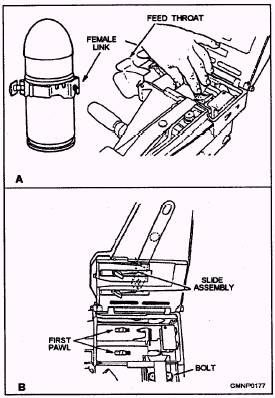
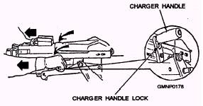
Figure 3-103.-Loading the Mk 19 Mod 3 machine gun. shown in figure 3-103. With the female link first, feed the belted 40-mm ammunition through the feed throat (fig. 3-103, view A) and into the feeder and across the first pawl (fig. 3-103, view B). Now, move the slide assembly to the left and close and latch the top cover. To charge the weapon, grasp the charger handles with palms down, as shown in figure 3-104, depress the charger handle leeks, and rotate the handles down. Then pull the charger handles sharply to the rear. When you
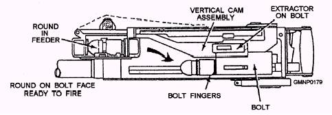
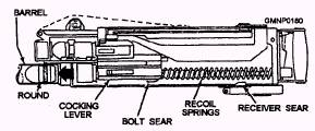
Figure 3-104.-Charging the Mk 19 Mod 3 machine gun. feel the bolt latch in the rear position, push the charger handles forward and up into the locked position. To load the first round, place the safety in the FIRE position and press the trigger. The bolt will spring forward and the first round will be loaded on the bolt face in the extractors. This is called the half-load position. Depress the charger handle locks and pull the charger handles to the rear a second time to load around into position for firing (full-load). Pulling the bolt back a second time (fig. 3-105) delinks the round from the belt. The curved rail on the vertical cam assembly forces the round down the bolt face, out of the extractors, and into the bolt fingers. FIRING.- With the weapon in the full-load condition, pressing the trigger causes the receiver sear to release the bolt. The recoil springs force the bolt forward (fig. 3-106). As the bolt travels forward, the cocking lever is released and the bolt sear strikes the receiver plate, pushing it rearward. This movement of the bolt sear releases the firing pin, which strikes the primer and fires the round. RECOIL/EJECTING.- As a round is fired, recoil pressure from the burning propellant acts to force the bolt rearward (fig. 3-107). As the bolt moves rearward,
Figure 3-105.-MIK 19 Mod 3 machine gun loading operation. 3-52
Figure 3-106.-Mk 19 Mod 3 machine gun firing sequence. it extracts the spent cartridge, cams the next round down the bolt face, which forces the spent cartridge out the bottom of the gun, and moves the feeder drive levers to move the next round into position for delinking. Firing will continue automatically as long as the trigger is depressed. When the trigger is released, the bolt is held in the rear position by the sear assembly with a round in the bolt fingers. The Mk 19 Mod 3 machine gun should be kept clean and lubricated as prescribed in the U.S. Army TM 9-1010-230-10 and the appropriate Navy 3-M Systems MRCs. Detailed disassembly, cleaning, and troubleshooting procedures are also found in these two sources. |
 |
|
|
||