Custom Search
|
|
 
|
||
|
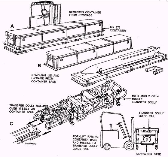
Handling Operations Now that you have some background information on various containers and handling equipments, let's put it to use. The next three figures in the text illustrate certain basic handling operations for Mk 13 Mod 4 and Mk 26 GMLS class ships. Refer to them frequently as we describe the major events. Take special note of the equipments being used Also, use a bit of imagination and remember the versatility of these items. NOTE Certain key steps or events have purposely been omitted from the general descriptions that follow. TARTAR HANDLING-CONTAINER TO DOLLY.- Figure 2-55 shows a typical Standard In this case, the missile is transferred directly from its container onto a dolly. View A shows a forklift truck moving a Mk 372 container to a designated handling area. Note that the forklift tines are lowered and the container rides near ground level. This orientation is the safe way, considering center of gravity and counterbalance factors. The forklift will deposit the container on a flat, even surface (either on a pier or A.E-type ship's deck). View B shows the container being prepared. The lid is unlatched lifted from the base, and hand-carried from the immediate loading area. That makes room for upcoming forklift and dolly movements. The center missile support (U-frame) is removed. The lower missile shoes are unlocked from the inner support assembly of the container. In view C, a Mk 6 Mod 2 or 4 dolly has been brought into position behind the container. When the dolly is aligned to the container, its wheeIs are locked (straight).
Figure 2-55.-A Standard MR missile handling sequence; container to dolly without roll. The dolly is pushed forward over the container until the guide rail openings of the dolly are over the upper missile shoes. At this point, the missile shoes are about 9 inches below the guide rail of the dolly. In view D, the forklift truck has reengaged the container. Carefully, the container is raised until the missile shoes enter the guide rail openings of the dolly. The dolly is pushed so the shoes enter the guide rail tracks/slots. Locking mechanisms are turned to secure the missile in the dolly. The forklift operator lowers the empty container to the ground (pier or deck). The forklift backs away and the loaded dolly is pushed to a staging area. The lid of the container is reinstalled and the empty container is removed from the area. The procedures described above pertain to an on-load operation. An off-load sequence is essentially the reverse-the missile is transferred from a dolly directly into a container. STANDARD HANDLING-ROLLING THE MISSILE.- In certain situations, a Standard missile must be rolled or turned 180. Figure 2-56 illustrates the key steps in this operation. In view A, a Mk 5 hoisting beam has been attached to the missile shoes. After the missile is unlocked from the container, a forklift carefully raises the loaded beam clear of the base of the container. This operation is often called decanning. View B shows the missile being lowered into a properly prepared Mk 8 dolly loading stand. When the upper ring halves of the roll ring assembly are resecured in place, the missile is rolled View C shows the dolly in position to be pushed over the load stand. (The upper ring halves are removed again.) This operation is the same as that described with view C of figure 2-55. In view D, the forklift is raising the loading stand to engage the missile to the dolly. Again, the operation is similar to view D in figure 2-55. Now use your imagination. The Mk 5 hoisting beam in view A of figure 2-56 could be replaced with a Mk 15 beam; that is, if Mk 79 handling bands were installed on the missile. Also, in view A, the container could be substituted with Mk 100 stowage adapters or a Mk 20 stowage cradle. (Do you get the idea of the "imagining" exercise?) In view B of figure 2-56, the load stand could be a Mk 20 cradle instead. The operations in views C and D of figure 2-56 would be the same using a cradle. In certain sequences, even the forklift truck can be replaced with an overhead crane/hoist. Again, handling equipments are very versatile. The conditions of the handling operation will dictate which equipments (or options) can be used. |
 |
|
|
||