Custom Search
|
|
 
|
||
|
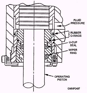
HYDRAULIC SEAL REPLACEMENT Most modern gun systems are loaded and positioned by hydraulic machinery. System pressures, in many cases, exceed 1,000 pounds per square inch (psi). As a Gunner's Mate performing routine maintenance on your gun, you need to be constantly on the lookout for hydraulic fluid leaking past the seals around pistons and operating shafts. When your system is leaking, it is telling you something. The seals are breaking down or are worn and could rupture at any time. Should the packings around a large high-pressure piston fail, you could dump 10 or 15 gallons of hydraulic fluid before the system can be secured. All leaks need to be reported, documented, and repaired as soon as possible. Leak Documentation When a leak is first discovered, it should be reported to your leading petty officer (LPO) and/or work center supervisor (WCS). Normally as the maintenance person, you will also be required to document the leak using the ship's 3-M Systems, Form 4790-2K. In the write-up, it is important to use proper terminology in describing the exact location and component where the leak exists. In describing what is required to correct the problem, it is helpful to include the part number and quantity of seals and other repair parts needed to do the job. Component names and part numbers are found in the IPB. Providing an exact description of the problem and the parts required to effect the repair serves two purposes. If, for some reason, you are not available to help when the repair is scheduled, other maintenance personnel will be able to identify the problem and its solution easily. Second, when a problem is documented, it is incorporated into the Current Ship's Maintenance Project (CSMP). The CSMP provides Navy managers at all levels with information concerning the readiness of the systems aboard ships. It is used to plan and coordinate maintenance actions in the work center and to put together overhaul packages for completion by tenders and shipyards. This documentation procedure not only applies to hydraulic leaks but to all other corrective maintenance you will perform. It is not normally necessary to document routine mechanical adjustments. However, if the adjustment is necessary due to replacement of a damaged or worn component, the circumstances surrounding the component replacement should be recorded. Types of Seals Before we go into the actual repair process, we need to describe some of the common types of seals used in ordnance equipment. A normal high-pressure packing consists of a U-Cup seal and a wiper ring. The U-Cup seal is installed with the cup facing the pressure it is to contain. As hydraulic pressure is applied, the cup falls and the sealing edge is held against the shaft or piston surface. The wiper ring keeps the piston surface clean to prevent wear of the U-Cup seal. These seals are often contained in an insert, called a packing gland, that is bolted or screwed into a valve block or cylinder. The packing gland allows for easy replacement of the seals since it can be removed. Figure 12-8 shows these seals and how they are installed in an actual valve block The U-Cup seal is contained in a machined groove on the inside surface of the packing gland. The wiper ring is installed into another machined groove at the outside edge of the gland. Note the rubber O-ring seal in the machined groove around the outside of the packing gland. Since both are machined to very close dimensions, an O ring is sufficient to contain any seepage that may occur. O rings are used throughout ordnance equipment in low-pressure sealing applications.
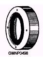
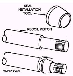
Figure 12-8.-A typical high-pressure hydraulic seal. Another type of seal you may encounter is the encased seal (fig. 12-9). This type of seal is found where rotating shafts exit gearcases or other fluid-filled reservoirs. As the name implies, the seal is encased in a metal housing. Sealing surface tension around the rotating shaft is maintained by a spring located under the lip of the seal. The metal case of the seal allows it to be pressed into the component casing. Seal Replacement In replacing hydraulic system seals, you must take care not to contaminate the system. Contaminates in a hydraulic system can have devastating effects. Damage can range from accelerated seal wear to the total destruction of pumps, valves, and drive units. Using some simple precautions can help make sure your system remains free from contamination. First, make sure the area around the component you are going to disassemble is thoroughly cleaned Second, after a component is removed, coverall exposed openings into the system with rags. Components removed for access can be reinstalled with their bolts turned finger tight. Reinstalling components and their retaining bolts also helps you to keep track of them. Last, make sure the component and the area it is to be reinstalled into are thoroughly cleaned. Anything you can do to limit hydraulic system exposure to outside conditions will help you maintain a system free of contamination. Seal replacement often requires the use of special tools. A good example of this is the tool used to reinstall the packing gland over the end of the recoil piston (fig. 12-10). The tool is in the form of a ring, tapered on the outside, that is slid over the threaded end of the recoil piston and up against the squared end of the enlarged section of the piston. The tapered outside of the tool allows the sealing surface of the U-Cup seal, which is fitted into a machined groove inside the packing gland, to slide easily past the squared end of the enlarged section of the recoil piston. The disassembly and reassembly of major gun system components are described in the system maintenance manual. Any special tools needed are identified throughout the procedure as required. All gun mount special tools are illustrated and described in the system maintenance manual.
Figure 12-9.-Encased seal.
Figure 12-10.-Use of a hydraulic seal replacement special tool. The disassembly of hydraulic equipment inevitably causes air to get into the system. Your system will be fitted with vent plugs for releasing this air. Air is compressible and can cause your system to operate erratically or sluggishly. Be sure to follow the detailed instructions found in your systems maintenance manual or the appropriate MRC for venting air from the hydraulic system. You may also find it necessary to replenish your system with hydraulic fluid after a repair is completed. The procedure for adding fluid to the system can be found both in the system maintenance manual and on a situation requirement (R) MRC. You will normally follow the procedure described on the MRC. Additional information on seals and seal replacement can be found in Fluid Power, NAVEDTRA 12964. |
 |
|
|
||