Custom Search
|
|
 
|
||
|
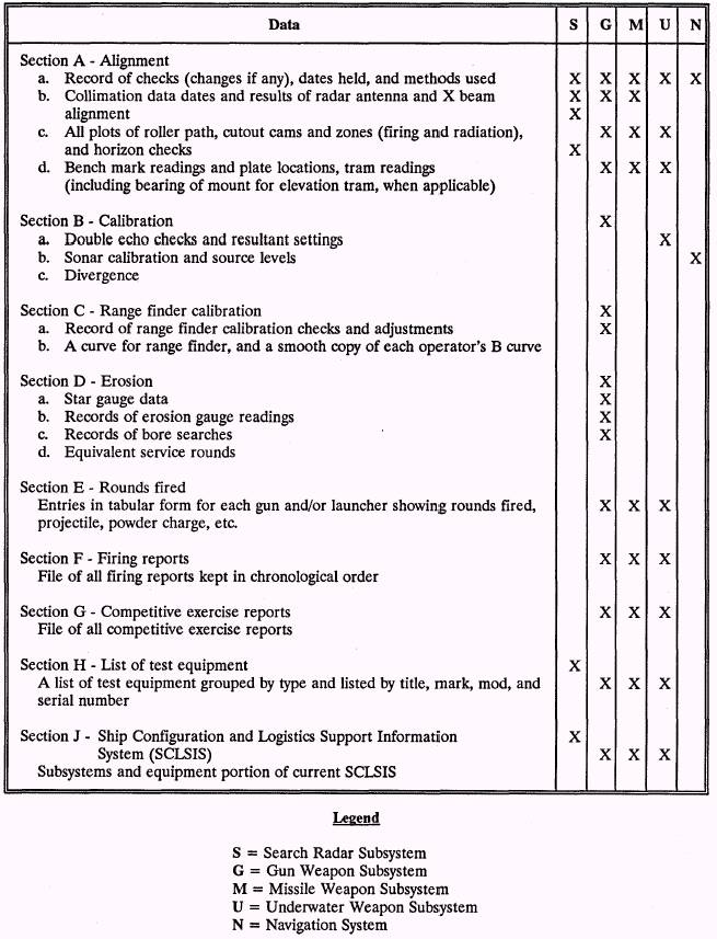
RADAR ALIGNMENT LEARNING OBJECTIVES: Discuss the importance of radar alignment on a guided missile battery. All the elements of a guided missile battery are aligned in the same manner as a conventional weapons battery. There is, however, one additional step you must accomplish before the physical alignment of the battery. You must first align the radar reference beam and the boresight telescope of the radar antenna. This can be accomplished by using a shore tower approximately 100 feet high and at least 1,300 feet from the ship. The tower must be equipped with an optical target and a tunable radar transmitter. On some missile systems, the radar beam is used as the reference for this alignment. The radar beam is trained and elevated to the tunable radar transmitter and electrically aligned. The boresight telescope is then adjusted to the optical target and locked in place. In other missile systems the boresight telescope is the reference. The boresight telescope is trained and elevated to the optical target on the tower and then the radar beam is aligned to the tunable transmitter. This is the most critical alignment, because, in both cases, the boresight telescope, after alignment, becomes the only reference line of sight for the director. Benchmark data is provided to check this optical alignment periodically. The above explanation is for dry dock alignment performed by shipyard personnel, perhaps assisted by the ship's force personnel. When the ship is afloat, the radar reference beam is again checked by the ship's force. While at the pier, the shore towers are used. At sea, all the guided missile ships will use bow and/or stern towers installed according to current NAVSEA instructions. Each tower will contain an optical boresight target, a capture antenna, and a track and guidance antenna. FINAL ALIGNMENT AND TEST LEARNING OBJECTIVES: Discuss the importance of testing after a battery alignment and recording the results in the Combat Systems Smooth Log. The success of a weapons system depends to a great extent upon the mechanical and electrical alignment of the system. Minor errors in synchro or dial adjustments can result in missing the target by a great distance. If any error corrections were made to train or elevation receiver-regulator dials, you must establish new alignment readings. Obtain the detailed instructions for your system and follow them with care. Upon completion of the train and elevation checks, the elements of the system are rechecked against their respective bench marks and new dial readings are recorded in the ship's battery alignment and fire control smooth logs. Although both of the above tests can and should be conducted by the ship's force, it would be wise to ask for technical assistance from a repair facility if you are unsure of the procedures. Modern ordnance installations are operated almost exclusively in automatic control, except under certain special conditions or in emergencies. Therefore, it is especially important for an installation to be aligned accurately for automatic operations. If the alignment methods described in this chapter are used so that the dials of each element are aligned accurately with the dials of the reference element, you should end up with a good alignment. It is advisable to check the results under conditions which approximate those under which the equipment will be used. The checks should be performed with the system in automatic control and with the parallax equipment functioning. If possible, select several targets with different bearings and at ranges that will be as close as possible to the mean battle range for the equipment. For antiaircraft installations, try to use air targets which are at an elevation angle near 45. The target should produce a slow bearing so that accurate tracking is not difficult. Train and elevate the director to track a target as accurately as possible, especially in train. When on target, the director-trainer will call "MARK" by telephone to the operators at their stations. The operator at each station observes the target through the boresight telescope or the boresight and makes a note of any train error present when the director is on the target. This should be done for targets at various bearings, some moving to the right and some moving to the left. In this check,some small error is to be expected because there is always some lag-and-lost motion in the follow-up servomechanisms. Regardless, the error observed when tracking to the left should be essentially equal to that observed when tracking to the right and should be in the opposite direction. If the errors do not change direction when the direction of tracking is changed or if they are considerably larger for one tracking direction than the other, a misalignment is indicated This can be corrected by adjusting the train synchros. Before any adjustment is changed, however, a careful analysis should be made to be certain that the error is not caused by some other factor. For example, a misalignment of the sight telescope could cause an error. This should be corrected by boresighting the telescope, not by adjusting the synchros. Adjusting the synchros, in this case, would result in firing errors. If, after careful analysis, an adjustment is made to the synchros, a check should be made to see whether or not a corresponding adjustment must be made to the dials or any other part of the system. As you can see, every component in a weapons system is linked either directly or indirectly to the others, as are the operators and maintainers of the equipment. You must think and act in terms of the weapons system as a whole. What you do, and how your equipment operates, will affect the operation of the system as a unit. Before undertaking any alignment tasks, you should become thoroughly familiar with the contents of SW225-AO-MMA-010/OP762, Align Theory, Theory of Combat System Alignment Manual. This publication will assist you in obtaining a general understanding of the total combat system alignment methods. It defines combat system alignment, why it is needed, and what it does and does not accomplish. The principles of alignment and the general reasoning behind the procedures involved in alignment are explained. Detailed instructions for the alignment of specific systems are not covered in this TRAMAN. The SW225/OP 2456 series, Total Combat System Alignment Manual, contains specific alignment procedures for each class of ship. This publication is intended to be used as a guide when performing combat system alignment. It is to be used in conjunction with PMS testing and maintenance. PMS tests are designed to check the proper operation of all the subsystems, either as a single entity (total combat system) or as individual subsystems. Although most PMS tests are not developed solely for alignment purposes, review of the results of those tests that provide alignment verification over a period of time will indicate trends toward out-of-tolerance alignment conditions. The importance of maintaining an alignment smooth log cannot be overemphasized. Upon completion of the alignment, data must be documented to provide information for future alignments and to inform responsible personnel of system and subsystem alignment status. A complete and accurate alignment data package is essential for effective combat system alignment. Upon completion of the initial, or a subsequent, alignment by a shipyard or support activity, an alignment report is submitted to the ship's commanding officer. The data in this report becomes the base line information in the Combat Systems Smooth Log for future system alignment verification. The Combat Systems Smooth Log is a perpetual record of all alignment, calibration, and internal ballistic data. The importance of maintaining the smooth log cannot be overemphasized. A general outline of data that should be included in the smooth log is provided in table 11-1. Reproducible forms for use in the Combat Systems Smooth Log are located in the back of SW225-AO-MMA-010/OP762. The Combat Systems Smooth Log, section J, contains weapon system configuration data from the Ship Configuration and Logistics Support Information System (SCLSIS) Manual for your ship. The central SCLSIS data base contains the configuration information related to each unit's installed and planned equipment hardware. It identifies the proper level of logistics support required to maintain each piece of equipment. Through the SCLSIS process, configuration data is passed to the Weapon Systems File (WSF) at SPCC, which is used to determine spare parts requirements for ships. The on-board availability of spare parts is critical to keeping your systems up and operational. Therefore, you should always make sure this section is 100 percent accurate. For more information on SCLSIS and SCLSIS reporting, see NAVSEA Technical Specification 9090-700A. SUMMARY The main role of a GM is to deliver the ordnance on target. Your weapon system may be fully operational, but if you cannot hit your target, it's useless. The importance of accurate battery alignment cannot be overemphasized. Although some alignment procedures are described in this chapter, it is more important that you know where to find alignment procedures and instructions that are written specifically for the systems you will be working with on a daily basis. Table 11-1.-Smootb Log Data and General Outline
|
 |
|
|
||