Custom Search
|
|
 
|
||
|
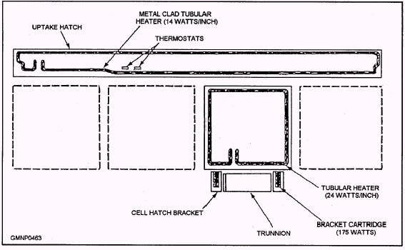
Actual Anti-Icing Systems The Mk 13 Mod 4 GMLS uses a heat source other than auxiliary steam. Twelve electrically controlled immersion heating elements are located within the heat exchanger tank of the Mk 13 Mod 4 GMLS. Each element is a 1/2-inch copper sheath about 6 feet long. It is bent into a loop that projects about 1 1/2 feet into the tank. The copper sheaths are heated by single-phase, 440-VAC, 60-hertz power. They are energized through a heater-controller panel located near the launcher control room. Tank fluid is heated as it flows across the elements. The Mk 41 VLS anti-icing system is designed to prevent a buildup of snow or ice that might prevent a cell or uptake hatch from opening during launch operations. The anti-icing system does not provide coverage of the strikedown hatch. Anti-icing must be manually enabled for each module individually at the launcher status panel. The main items of the anti-icing system are heaters and thermostats built into the uptake and cell hatch assemblies (fig. 8-37). The uptake hatch contains one tubular 14-watt-per-inch heater element and two thermostats that activate the anti-icing system when the temperature falls within the 33F to 43F range. Each cell hatch has three heater elements; two of the heaters are 175-watt cartridge elements that are built into the hinge brackets on either side of the trunnion. The third heater is a 25-watt-per-inch tubular element built into the cell hatch cover and located around the perimeter of the hatch. AIR-CONDITIONING AND VENTILATION SYSTEMS Air-conditioning and ventilation systems are used in GMLS areas for the general safety of equipment, personnel, and the ship. The purpose of these systems is to circulate air around vital system components. This circulated air maintains normal temperature and humidity levels within a space. Air-conditioning systems use ship-supplied chilled water, a cooling-coil unit, and fan-blower units to circulate cool air. Ventilation systems only use a fan-blower unit to circulate ambient (surrounding) temperature air.
Figure 8-37.-Module hatch heater elements. Launcher control rooms and missile magazines are always air-conditioned spaces. Some GMLSs use a separate ventilation system to cool their launcher carriages. Ventilation systems are usually thermostatically controlled to maintain space temperature ranges between (an average) 70F and 100F. Also, a majority of air systems have cutoff valves installed somewhere in the supply and exhaust lines. These valves should bear a Circle William damage control classification. Learn where these valves are located. They must be closed during nuclear, biological, and chemical (NBC) drills. Additionally, make SURE all air filters are cleaned properly on a strict maintenance schedule. That will keep these systems operating at peak efficiency. Magazine air-conditioning/ventilating systems can also serve an important secondary purpose. Consider a missile magazine with an installed or fixed CO2 system. If fire breaks out, the space will be flooded with CO2 extinguishing agent. The air system must be secured quickly to prevent the CO2 from being drawn out of the space. Normally, the CO2 system has a pressureoperated switch that interconnects to the electrical circuit of the air system. When the CO2 system activates, the switch secures the air system (turns off the blower). The air system should not be turned on for at least 15 minutes after CO2 discharge. This 15-minute time period serves as a cool-down period. The cool-down period prevents hydraulic fluids and lubricants from re-igniting when exposed to a new air supply. After the cool-down period, the space should be ventilated a full 15 minutes before anyone enters it. The air system removes the CO2 gas and restores air to a life-sustaining level. We will briefly examine the various air-conditioning and ventilation systems used in the GMLSs. Mk 13 Mods 4 and 7 GMLSs The magazine ventilating systems on the Mk 13 GMLSs use air, which is forced into the magazine, from the ship's air-conditioning system. It cools the missiles and inner structure (center column) equipment areas (fig. 8-38). Air enters the magazine through intake ducts under the cells. It flows up around the missiles and enters the inner structure through ventilation screens at the top of the structure. The exhaust ducts are in the center of the base. Mk 26 GMLS The Mk 26 GMLS and Mk 41 VLS use standard ship-operated air-conditioning units to cool their spaces. The Mk 26 has one unit that supplies the ICS and another that supplies the magazine. |
 |
|
|
||