Custom Search
|
|
 
|
||
|
INTERNAL COMPONENTS.- Access to components inside the EP2 console is through a large door on the back or two small doors on the front. The components accessible through the back door are the printed circuit (PC) cards on the wire-wrap backplane, fuses, manual handcrank solenoid controls, receptacles with polarizing key positions, electronic component circuit cards, terminal boards, and other miscellaneous components. All components in EP2 are identified by an electrical designation stamped (or applied) on or near each component. Accessible through the two front doors are rectifiers, low dc voltage power supplies, a rechargeable nickel-cadmium battery, a battery charger, and a fan for component cooling. The rechargeable battery provides dc power to launching system solenoids under two conditions. If a power failure occurs in the 115-VAC power distribution network during an operational cycle (that is, raising the hoist), the dc battery supply will activate automatically. The battery will provide a dc output for about 5 seconds and permit completion of the interrupted cycle. The second condition is used during maintenance or troubleshooting procedures in a normal power-off condition. System personnel activate the manual handcrank solenoids control and position a selected toggle switch. This actuates a particular solenoid and permits handcrank or handpump operation of a component (that is, extend or retract the launcher retractable rail). Electronics Panel, EP3 The EP3 electronics panel contains the electronic control and test equipment for launcher train and elevation power drives. The front of the EP3 panel
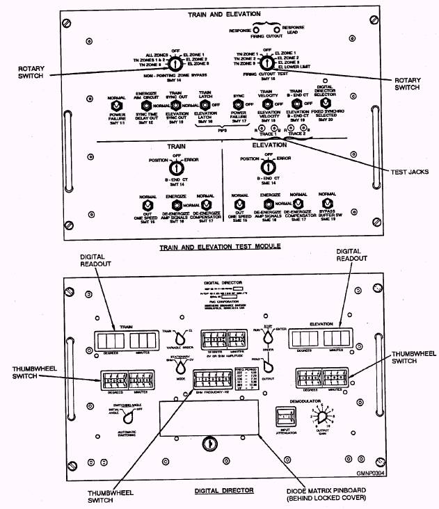
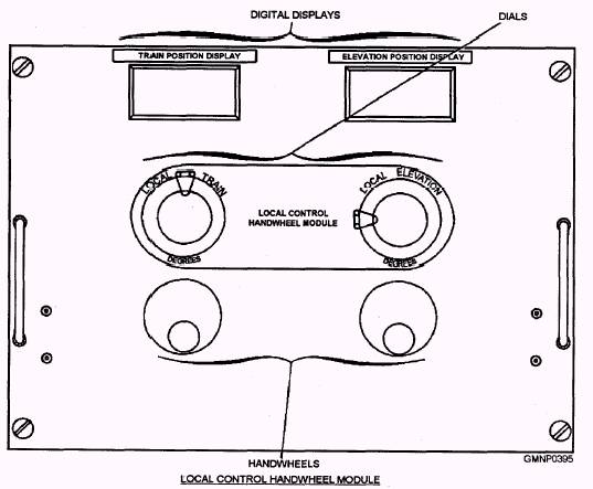
Figure 7-16.-Electronics panel, EP3 (sheet 1 of 2). (fig. 7-16) contains the train and elevation test module and the digital director (DD), the local control handwheel module (LCHM), and the electronic servo control unit (ESCU). The LCHM (fig. 7-16, sheet 2 of 2) generates train and elevation local control position order signals to point the launcher. Digital readouts on the LCHM show launcher train and elevation positions. Response signals from synchros in the train and elevation power drive receiver-regulators operate the digital readouts on the LCHM. The LCHM is the primary local control unit for the launcher and comes on-line automatically when local pointing is selected. During a HARPOON casualty mode, the LCHM is required to point the launcher. The test module is used to test train and elevation nonpointing zones, nonfiring zones, and synchronization of the power drives. It contains switches and jacks to select the tests and record traces. The DD is used to operate the train and elevation power drives in local control. It is also used with the test module and the electronic servo control unit (ESCU) to check and test power drive operation. The DD has rotary and thumbwheel switches to control the power drives. Digital readouts indicate DD output in degrees and minutes for train and elevation. A diode matrix pinboard, behind a locked cover, generates the stationary position orders for load, strikedown, and jettison operations. The ESCU is located in the rear of EP3 and is the servo amplifier for the train and elevation power drives. The unit consists of a solid-state amplifier with 13 PC cards on the upper half and amplifier controls and test jacks on the lower half. MK 26 GMLS AND MODS LEARNING OBJECTIVES: Explain the purpose/function of the Mk 26 GMLS major components with Mod differences.
Figure 7-16.-Electronics panel, EP3 (sheet 2 of 2). The Mk 26 Mods 0 through 5 GMLSs (fig. 7-17) have been designed to be an extremely versatile and sophisticated addition to the missile community. They are installed aboard the DD-993 Kidd-, CGN-38 Virginia-, and CG-47 Tilconderoga-class ships. This GMLS possesses one of the quickest reacting and fastest firing rates of any comparable dual-arm system. Constructed with advanced solid-state electronic, hydraulic, and mechanical features, the Mk 26 GMLS is compatible with a variety of fire control systems (Standard, ASROC, and AEGIS). The system also handles a mixed arsenal of missiles including Standard SM-1, SM-1A, and SM-2 rounds and the ASROC (both torpedo and depth charge configurations). |
 |
|
|
||