Custom Search
|
|
 
|
||
|
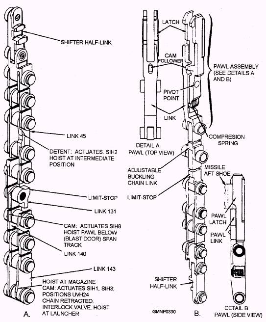
Hoist Assembly The components of the hoist assembly (fig. 7-11) perform all vertical transferring of the missiles. The hoist chain (fig. 7-12) is an open-end roller and link-type chain with cam-type projections and detentes on some specific links. They actuate interlock switches and valves, couple with the shifter half-links on the hoist pawl units, and act as travel limit-stops.
Figure 7-12.-Hoist chain component A. Hoist chain; B. Outer hoist pawl. The chain stowage housing, mounted in the inner structure, stows a majority of the length of the chain when it is retracted. A small section of chain remains exposed on the drive sprocket and in the chain shifter. The hoist B-end hydraulic motor connects to a speed reducer and drive sprocket that drives the chain. The hoist chain shifter is a hydraulically operated device located between the drive mechanism and the curved tracks. It raises or lowers the hoist chain's shifter half-link into alignment with either the inner or the outer hoist pawl unit's shifter half-link (see fig. 7-12). Two curved track assemblies, one for the inner ring and one for the outer ring, serve to guide the hoist chain and connected pawl unit. They pivot out and up to the magazine rail of the cell at the selected hoist position, Additionally, the hoist pawl units are stored in their respective curved track sections when the hoist chain is fully retracted at the magazine position. A hoist pawl unit is extended to engage the aft missile shoe to load a missile. As the hoist pawl reaches the intermediate position (the point where the aft shoe of the missile rests), a cam follower forces the pawl latch to pivot sufficiently away from the pawl link to clear the aft shoe. At the same time, other surfaces on the hoist pawl are unlocking and caroming the cell latch open. The pawl link contacts the bottom of the shoe. A compression spring returns the pawl latch to its normal position, closing over the top of the shoe. The missile is then raised to the guide rail of the launcher. There the aft-motion latch mechanism extends and pivots the pawl latch to release it from the aft shoe. The missile is now secured to the launcher rail and the chain retracts to the magazine. Associated with the hoist assembly are the inner and outer retractable rails of the magazine. (See fig. 7-11.) When either rail extends, it forms a continuous track between the magazine rail of the station at the hoist position and the fixed rail mounted on the carriage base ring. With both retractable rails retracted, clearance is provided betweenthe missile heads and the RSR during RSR rotation. Only one retractable rail may extend at a time. Magazine Hydraulic Power Supply The magazine power supply furnishes hydraulic pressure to operate components of the RSR/hoist power drive (refer to fig. 7-2) and other units in the magazine (that is, retractable rails, RSR positioner, and chain
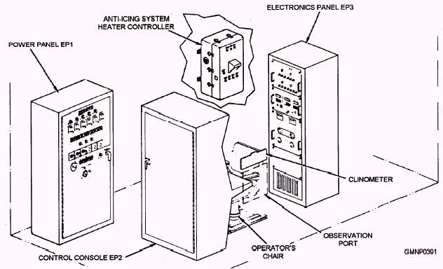
Figure 7-13.-Launcher control station. shifter). The power drive consists of an electric motor that drives a hydraulic A-end pump. The pump provides hydraulic fluid pressure to either the RSR B-end or the hoist B-end. A hydraulic control valve shifts or redirects the output of the A-end to the selected motor. It is not unusual to see this type of arrangement (one pump or A-end capable of driving two individual motors or B-ends) in ordnance systems. In the Mk 13 GMLS, the RSR cannot index while the hoist is cycling (and vice versa). This type of power drive is very practical in design and results in a smaller, more compact unit. Harpoon Warmup A Harpoon missile does not require warmup in the magazine, but does require about 10 seconds' warmup on the guide arm. Harpoon warmup power is applied through the fin opener arm (23-pin) contactor. |
 |
|
|
||