Custom Search
|
|
 
|
||
|
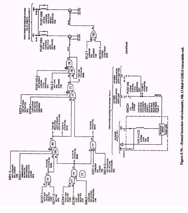
COMPLETING THE RETRACT CYCLE.- When the launcher rail is fully retracted, proximity switch SIL1 activates. The 1 and 2 outputs from its inverter-buffer affect the retract circuit in two ways. First, the SIL1-2 input (Group C) to OR-AND gate 77-39 now goes low. The change in input status produces a low output at 77-36. The low-output signal turns off the NPN transistor and de-energizes PC67-K5A relay coil. Since it is a detented relay, its contacts remain closed to the LHL1-LC1 solenoid driver. The second result of SIL1 activating affects OR-gate 132-6. Its SIL1-1 input now goes high. The output signal produced at 132-14 goes high. It turns on the other NPN transistor (67-44) that energizes the PC67-K5B relay coil. This coil, being the reset coil of PC67-K5, causes the contacts of the relay to open. The high input to the solenoid driver of LHL1-LC1 is thereby removed. The solenoid de-energizes and returns to neutral. The other input to OR-gate 132 is QCS21-1, system start reset. This input is high whenever summary circuit QCS21 is activated. The purpose of summary circuit QCS21 is related to safety. It is activated during system start or turn on procedures. When activated, QCS21 produces a high output. This signal is supplied to every reset coil of all the guide arm component relays. Energizing each reset coil prevents the accidental movement of equipment. After initial light off and when the system is ready to operate, QCS21's output goes low. Step-Load Circuit The step-load circuit centers around the two inputs of Group D in figure 5-78. The circuit is used to retract a loaded launcher rail if jettison operations must be performed in step control. Therefore, many of the conditions of an auto-not-unload mode must still be satisfied for the step-load cycle. When the console operator changes modes, the QCX7-1 (Group A) input to 77-40 goes low. This change effectively disables the entire retract circuit and PC67-K5A cannot be energized. As the console operator switches into step-load, the QCX4-1 (Group D) input to AND gate 77-8 goes high. This action only satisfies one of the required inputs to the circuit. To retract the launcher rail, the console operator depresses push button SML1. The switch provides an input signal to its buffer circuit. The unflagged output line of the circuit goes high. The high SML1-1 input applied to 77-10 activates the AND gate. It provides a high output at 77-18. This signal satisfies the OR-AND gate's (Group A) inputs and the launcher rail retracts. Step-Exercise Circuit The step-exercise circuit centers around the Group E inputs on figure 5-78. When the three input conditions to the Group E AND gate are satisfied, a high is produced at 77-54. The high is applied to 77-45 of the OR-AND gate in Group B. The remaining circuit inputs and operations are the same as a step-load cycle. Notice that all Group A inputs are low at this time and are not used. Take a minute to review the various retract cycles performed by this solid-state control circuit. It is important that you understand the principles involved. EXTEND LAUNCHER RAIL The launcher rail automatically extends following missile firing or jettisoning operations. After the rail is empty, the aft-motion latch and arming device retract. The forward-motion latch also locks in place. These, and other conditions, complete the auto-not-unload circuit to energize extend solenoid LHL1-LC2. The hydraulic-mechanical actions are then initiated to re-extend the rail. In step-load and exercise modes, depressing the extend push button initiates the circuit to energize LHL1-LC2. We will not go into a detailed analysis of the extend circuit shown in figure 5-79. It is very similar to the retract circuit in terms of logic gate operation and sequence of events. Refer to figure 5-78 as the following paragraphs describe the various signal paths. Auto-Not-Unload Circuit The following logic inputs are involved with the extend auto-not-unload circuit. Locate them and trace their outputs on figure 5-79. 1. QCX7-1-Auto-not-unload selected 2. QCY1-2-Not aim 3. SIR1-2-Not launcher rail loaded 4. SIA2-1-Arming device retracted and forward-motion latch locked 5. SID2-1-Dud jettison retracted 6. KPX4-1-Launcher power unit motor contactor energized 7. PC67-K5-2-Not retract launcher rail cycle (detented) 8. SIL2-2-Not launcher rail extended 9. SIL2-1-Launcher rail extended 10. QCS21-1-System start reset When the first eight inputs in the above list are satisfied (high), PC67-K6A will energize. Its contacts close to activate the solenoid driver circuit. LHL1-LC2 solenoid coil energizes and the launcher rail extends. When the rail is extended, proximity switch SIL2-1
activates. The inverter-buffer outputs change and SIL2-2 (item #8) goes low to de-energize PC67-K6A. The SIL2-1 input (item #9) goes high to energize PC67-K6B (reset). This action de-energizes LHL1-LC2 that returns to neutral. |
 |
|
|
||