Custom Search
|
|
 
|
||
|
TRAIN AND ELEVATION LOCAL CONTROL UNIT The train and elevation local control unit (refer to fig. 5-59) is on top of the EP2 panel. It contains the gun mount position synchros used when exercising and testing the train and elevation systems. The control unit also contains four synchros (fig. 5-67) and the gearing which produce train and elevation order signals. DISPLAY PANEL EP3 Display panel EP3 (refer to fig. 5-59) contains only those components mounted on the front panel face. All indicators are protected by a sealed waterproof door. The door can be unlatched and swung down for easy access to burned out light bulbs. GUN MOUNT CONTROL SYSTEM COMPONENTS Components of the gun mount control system are located throughout the gun mount (fig. 5-68 and table 5-19), generally near the equipment with which the component functions. Connection boxes throughout the gun mount interconnect the panels with motors, proximity switches, photocells, solenoids, the fuze setter, anti-icing heaters, and the firing pin. Many of the control system components were discussed in the beginning of this chapter. Only a brief description will be given on how they interact on the control system of the Mk 45. Solenoid units controlled by control circuits initiate gun loading and unloading cycles. Control circuit interlock switches sense component and round positions. Control switches select modes of control (AUTO, STEP) and type of operation (LOAD, UNLOAD, and so on). Circuit cards contain electrical and logic circuits that use interlock and control switch input signals to trigger solenoids; logic and electrical circuits also control the fuze setter. Indicating lights on the panels indicate equipment and round position, switch status (activated, deactivated), and solenoid status (energized, de-energized). Segmented readout displays give numerical quantities that represent rounds of each type in the loader and test or fault codes. A wire- wrap backplane contains pins and connectors to interface the circuit cards. Connection Boxes Connection boxes serve as terminals for cabling between EP2 and the switches, solenoids, fuze setter, and firing pin. There are two types of connection
Figure 5-67.-Train and elevation local control unit, back of panel.
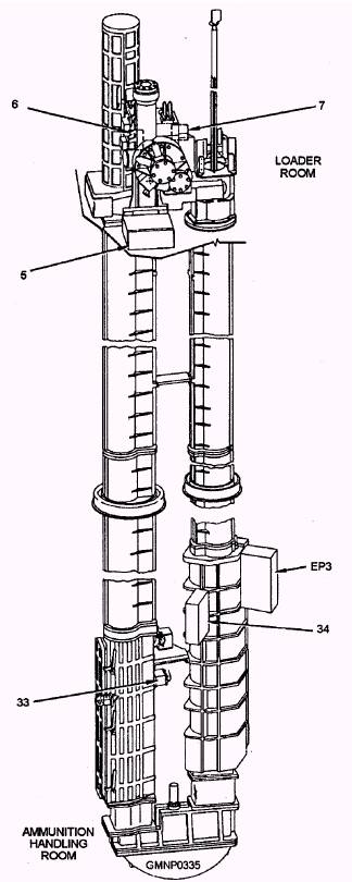
Figure 5-68.-Gun mount control system components (sheet 1 of 3).
Figure 5-68.-Gun mount control system components (sheet 2 of 3).
Figure 5-68.-Gun mount control system components (sheet 3 of 3). Table 5-19.-Gun Mount Control System Components
boxes-jack boxes (fig. 5-69) and terminal boxes (fig. 5-70). Some boxes also serve as connection points for distributing electrical power from EP1 to the lights, the heaters, and the motors. Solenoid Units The solenoid units (refer to fig. 5-14) convert an electrical signal from logic circuits into a hydraulic output, which initiates a mechanical motion. Each solenoid unit consists of two coils, a lever arm, a circuit board, a pilot valve, and a housing with a cover and cable jack. These solenoid units are often mounted on a solenoid valve assembly. Six separate solenoid valve assemblies, each with up to four solenoid units, are mounted at various points on the gun mount. |
 |
|
|
||