Custom Search
|
|
 
|
||
|
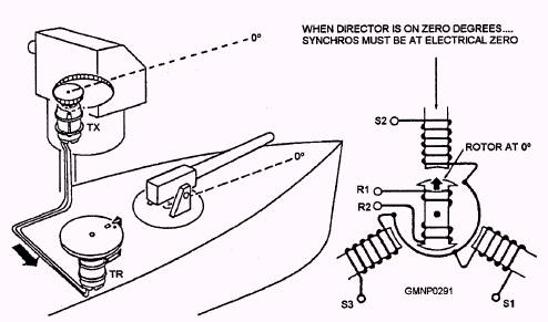
ELECTRICAL ZERO If synchros are to work together properly in a system, it is essential that they be correctly connected and slimed in remeet to each other and to the other devices, such as directors and guns, with which they are used. Needless to say, the best of ordnance equipment would be ineffective if the synchros in the data transmission circuits were misaligned electrically or mechanically. Since synchros are the heart of the transmission systems, it only stands to reason that they must be properly connected and aligned before any satisfactory shooting can be expected.
Figure 5-28.-System zero. Electrical zero is the reference point for alignment of all synchro units. The mechanical reference point for the units connected to the synchros depends upon the particular application of the synchro system. As a GM on board ship, your primary concern with the mechanical reference point will be the centerline of the ship for gun train and the standard reference plane for gun elevation. Remember that whatever the system, the electrical and mechanical reference points must be aligned with each other. Atypical example of proper alignment is a TX-TR synchro team coupled to a gun director, so adjusted that the gun position can be read on the TR dial. The gun director is at zero when the gun points directly toward the bow of the ship (fig. 5-28). A TX is coupled mechanically to the director, and a TR is connected electrically to the TX. If this system were setup without paying any attention to the position of the TX rotor, it would indicate the gun position accurately if the TR dial were set on zero when the gun director read zero. If the same synchros remained in the same system, it would not be necessary to position them more accurately. Sometimes TRs and TXs become defective and must be replaced. If another TX were put into this system without checking the TR dial, its rotor probably would be positioned differently from that of the original TX. The TR would follow the new TX, and the TR dial would read incorrect y. To overcome this difficulty, a zero degree point is needed, which is standard for all synchros. In the preceding example of the gun director, the system first should have been aligned so that all synchro rotors were at electrical zero, and all dials read zero when the gun director was on zero degrees. Then, any synchro could be replaced, without introducing error into the system, by installing the new synchro with its rotor on electrical zero when the gun director was on zero degrees. The electrical zero provides a standard way of aligning synchro units when they are connected together in a synchro system. There are two ways this alignment can be accomplished. The most difficult way is to have two GMs, one at the transmitter and one at the receiver or control transformer, adjust the synchros while talking over sound-powered telephones or some other communication device. The better way is to align all the synchros to electrical zero. Units may be zeroed individual y and only one GM is required to do the work. Another advantage of using electrical zero is that trouble in the system always shows up in the same way. For example, in a properly zeroed TX-TR system, a short circuit from S2 to S3 causes all receiver dials to stop at 60 degrees or 240 degrees. In summary, zeroing a synchro means adjusting it mechanically so that it will work properly in a system where all other synchros are zeroed. This mechanical adjustment is accomplished normally by physically turning the synchro rotor or stator. |
 |
|
|
||