Custom Search
|
|
 
|
||
|
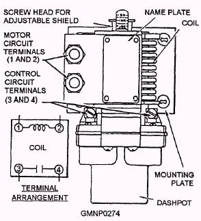
OVERLOAD RELAY.- The overload relay (fig. 5-12) consists of a coil, a plunger, a dashpot, and a pair
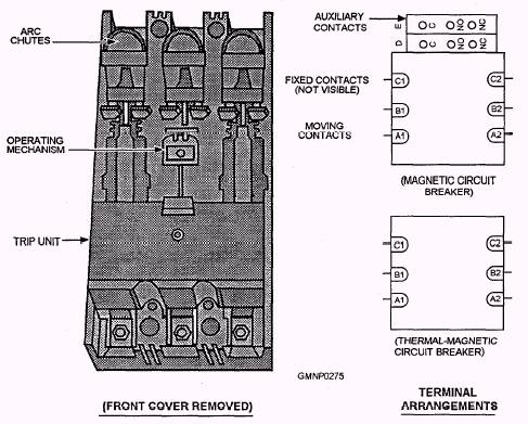
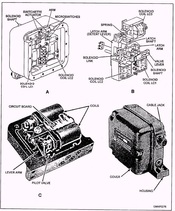
Figure 5-12.-Over1oad relay. of switch contacts. The plunger is attached to a disk suspended in an oil-filled chamber (dashpot). The coil connects in series with an associated 440-volt motor supply circuit and the switch contacts are in a 115-volt start-and-run circuit for the motor. During normal operation, the magnetic flux induced by the coil is not great enough to cause an appreciable movement of the plunger. However, if an overload of sufficient magnitude and duration occurs, the increased current through the coil draws the plunger upward. When the plunger and disk reach the end of their upward travel, the normally closed contacts open in the 115-volt start-and-run circuit, de-energizing the motor contactor which opens the 440-volt motor supply circuit. With the motor circuit open, the overload relay plunger drops and the relay resets. Since the dashpot retards upward movement of the plunger disk, the circuit does not break instantaneously during an overload. Two conditions determine the delay time: (1) the size of the orifice in the plunger disk through which the oil must pass and (2) the magnitude of the overload (strength of the magnetic field). Circuit Breakers Solenoids Circuit breakers (fig. 5-13) have two purposes: (1) to perform switching functions and (2) to provide overload protection. Each circuit breaker consists of a housing, a seaIed trip unit, three movable contacts, three fixed contacts, and three arc chutes. Gun mount control systems use two types of circuit breakers-the magnetic trip and the thermal-magnetic trip. Magnetic trip circuit breakers are used in the 440-volt power supply lines. They provide instantaneous protection against current surges up to 1,400 percent above the rated value of the circuit breaker. These circuit breakers have a set of auxiliary contacts (microswitches) that are wired into the control circuit to indicate the actual position of the circuit breaker contacts. Thermal-magnetic circuit breakers are used in the 440-volt supply lines to the control transformer and in the gunhouse heating and ventilating supply lines. These circuit breakers provide instantaneous protection against current surges up to 700 percent above the rated value of the circuit breaker. A bimetal element, connected in series with a coil, provides the protection against sustained overloads. Solenoids convert electrical inputs from control circuits into mechanical outputs that actuate mechanical linkage or hydraulic valves. All the solenoids consist of a coil and a movable core or armature. When the coil is energized, an electromagnetic field is created that either pulls or pushes the core. A mechanical linkage is attached to and travels with the core. In response to core movement, the linkage moves something. In most cases, that "something" is a small hydraulic valve (known as a pilot valve). Shifting the pilot valve redirects system hydraulic fluid to (for example) a piston. The piston is made to move so it extends or retracts a particular GMLS or gun mount component (e.g., a latch). The newer type of solenoid housing used in the Mk 45 gun system or Mk 13 Mod 4 and Mk 26 GMLSs (fig. 5-14) includes a nondetented two-solenoid configuration and pilot valve. (The function of the circuit board is described in a later section of this chapter.) This unit virtually replaces the older types of solenoid housings that were attached to large valve blocks to control the operation of hydraulic equipment. The small pilot valve in this solenoid unit controls the flow of hydraulic fluid to system operating pistons.
Figure 5-13.-Circuit breaker and terminal arrangements.
Figure 5-14.-Solenoid assembly. While many times smaller, these units efficiently perform the same function as the large solenoid housing and valve block configurations. These units are also much easier to maintain. When a solenoid malfunctions, the entire unit is removed and replaced simply by removing four bolts. The unit requires no adjustment and, because of its configuration, it also requires fewer hydraulic seals that can leak and lead to time-consuming repairs. Therefore, a solenoid plays an important role in GMLS and gun mount operation. It serves as the primary link between the electrical control system and the GMLS's hydraulic system. The solenoid assembly shown in figure 5-14 is the type used by the Mk 13 Mod 4 and Mk 26 GMLSs and the Mk 45 gun mount. The housing of the assembly also serves as part of the hydraulic valve block. Energizing either coil pivots the lever arm. It shifts the (one) pilot valve to redirect hydraulic fluid to the associated valve block. De-energizing the coils allows the return spring to shift the pilot valve back to neutral. |
 |
|
|
||