Custom Search
|
|
 
|
||
|
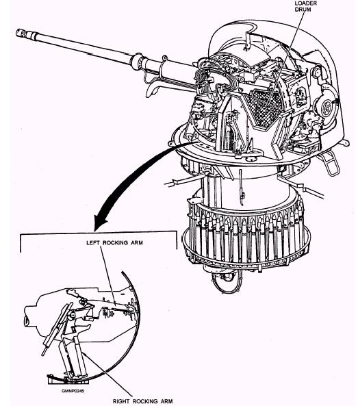
AMMUNITION-HANDLING SYSTEM The ammunition-handling system (fig. 4-50) for the gun mount moves ammunition from the revolving magazine to the last station loader drum where the ammunition is subsequently deposited into the transfer tray, rammed, and fired. The ammunition-handling system holds a maximum of 80 rounds of ammunition. When around is fired, each of the other rounds advances one position. The ammunition-handling system consists of the revolving magazine, the screw feeder and hoist system, the right and left rocking arm assemblies, the loader drum assembly, and the hydraulic power unit. The entire ammunition-handling system moves with the gun mount in train. The loader drum, which is mounted within the slide, moves with the gun in elevation. The hydraulic power unit, mounted on the carriage, provides the hydraulic pressure to operate components of the ammunition-handling system. A hydraulic motor drives the revolving magazine and the screw feeder and hoist. Hydraulic cylinders drive the rocking arm and loader drum assemblies. Ammunition is manually loaded into the revolving magazine, which holds 70 rounds. The ammunition is held vertically in two concentric circles of stowage cells; each circle holds 35 rounds. The revolving magazine turns when the hydraulic motor rotates the screw feeder.
Figure 4-50.-Ammunition-handling system. During rotation of the revolving magazine and screw feeder (fig. 4-51), around moves from the inner circle of stowage cells to the screw feeder. When a round leaves the inner circle of cells, around from the outer circle replaces it, leaving an empty stowage cell in the outer circle. When a round reaches the screw feeder, it is lifted in a spiraling reamer by hoist lift pawl assemblies of the hoist as the screw feeder rotates (fig. 4-52). The screw feeder, with a capacity of six rounds, delivers a round to the rocking arms. The rocking arms alternately raise the rounds to the loader
Figure 4-51.-Movement of rounds in revolving magazine.
Figure 4-52.-Ammunition flow diagram. drum (fig. 4-53). While one rocking arm is lifting a round to the loader drum, the other arm is returning empty to take the next round from the screw feeder. The loader drum has a capacity of four rounds. As the loader drum receives around from the rocking arm, it rotates to deposit the round in the last station loader drum and then into the transfer tray for subsequent ramming and firing (fig. 4-54). The last station loader drum is the last station of the ammunition-handling system; a round at this station can advance to the
Figure 4-53.-Movement of rounds from screw feeder to loader drum.
Figure 4-54.-Movement of rounds in loader drum. transfer tray only when all conditions of the firing circuit are satisfied. Upon completion of the firing circuit, the round in the last station loader drum is moved onto the transfer tray, rammed, and fired. At the same time, a rocking arm takes a round from the screw feeder to the loader drum. The screw feeder lifts around to replace the one removed by the rocking arm, and the revolving magazine delivers another round to the screw feeder.
Figure 4-55.-Gun-loading system general components. |
 |
|
|
||