Custom Search
|
|
 
|
||
|
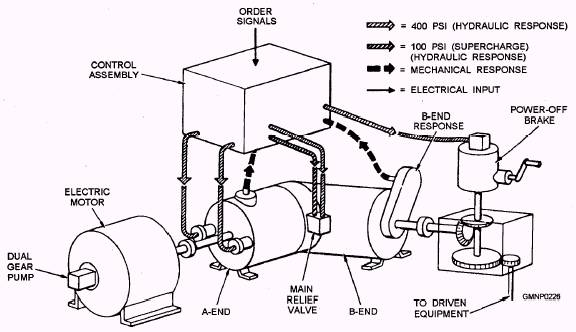
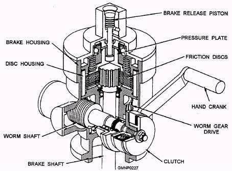
POWER-OFF BRAKE The power-off or brake of a B-end of a CAB type of power drive is connected to the output drive shaft of the motor of the B-end. (Refer to fig. 4-34.) When the brake is released, the power drive and the driven equipment are free to move. When the brake sets, it halts the movement of the equipment during a power failure. When the brake is set, it secures the equipment against the roll and pitch of the ship. It also provides for manual hand crank operations during emergency, installation, or maintenance procedures. Some GMLSs use a pneumatic drive mechanism instead of a hand crank, but the force is still applied to the power-off brake. The main components of a power-off brake are shown in figure 4-35. The lower end of the brake shaft is coupled to the output shaft of the B-end through a gear reduction unit. The other end of the brake shaft is splined to a set of inner friction discs. These inner discs are alternated with outer friction discs. The inner discs rotate with the brake shaft as the B-end turns. The outer set of friction discs is splined to a disc housing. The disc housing and outer discs are fastened to a worm gear drive. The worm shaft extends outside the brake housing and provides for either manual or pneumatic drive connections. A spring-loaded pressure plate at the top of the brake housing bears against the upper inner disc. The pressure plate is operated by a brake-release piston. Braking action occurs when the pressure plate presses the rotating inner discs into (friction) contact with the stationary outer discs. Through a positive gear-drive relationship between the brake shaft and the drive shaft of the B-end, the load (launcher) comes to a halt. Figure 4-36 shows a simplified schematic of the "set" and "released" positions of a power-off brake. When the power drive is secured (view B), there is no
Figure 4-34.-Interaction between a basic CAB type of power drive and a control assembly.
Figure 4-35.-Power-off brake. hydraulic fluid pressure (normally servo fluid pressure) on (or under) the brake-release piston. The springloaded pressure plate forces the friction discs into a braking engagement. Manual or pneumatic drive can now be accomplished by rotating the worm shaft, commonly called "driving through the brake." During normal power drive operation, servo fluid pressure is ported to the brake-release piston. By "lifting the brake," the friction discs separate, as shown in view A. This action permits free rotation of the brake shaft and the drive shaft/equipment of the B-end. When an operating power drive is shut down, either normally or through a power failure, a power-off brake solenoid ports the servo fluid pressure to the tank, The pressure plate springs "set the brake." Should a sudden power failure occur, the equipment will not come to a
Figure 4-36.-Power-off brake operation. screeching, abrupt stop. Hydraulically controlled valves in a nearby valve block govern or meter the servo fluid of the piston returning to the tank. This action quickly sets, releases, sets (and soon) the brake to bring the equipment to a smooth and controlled stop. |
 |
|
|
||