Custom Search
|
|
 
|
||
|
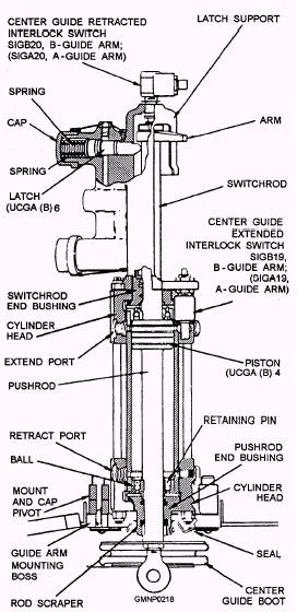
CENTER GUIDE HYDRAULIC COMPONENTS The hydraulic components of the center guide include the following: 1. A solenoid assembly 2. A directional control valve 3. A hydraulic cylinder 4. Two latches All of the components are mounted in the guide arm and are located directly above or near the center guide casting. The solenoid assembly (shown in figures 4-24 and 4-25) is identified as LCGA(B)l and LCGA(B)2. It is a detente type of unit that is mounted to directional valve UVGA(B)22. Hydraulic fluid from the solenoid assembly controls the position of the directional valve. The center guide cylinder (fig. 4-26) contains a movable piston UCGA(B)4 and four ball type of check valves. These check valves function to restrict fluid flow and slow down or cushion part of the stroke of the piston. The lower pushrod of the piston connects to the center guide casting and moves it. The upper switchrod (and arm) of the piston actuates the extended and retracted interlock switches SIGA(B)20 and SIGA(B) 19, respectively. The two spring-loaded latches UCGA(B)5 and 6 (refer to figs. 4-24 and 4-25) extend outward to engage the arm on the switchrod. The upper latch slides under the arm to lock the center guide in its retracted position. The lower latch slides over the arm to lock the center guide in its extended position. When the GMLS is secured, the center guide is normally in the retracted position. It is held thereby the upper latch. After the GMLS is activated, PA is distributed throughout the hydraulic system. Both latches are automatically retracted when PA overcomes latch spring pressure. Since the solenoid is detented, PA is also routed through it and the directional valve to pressurize the bottom (or retract) side of the cylinder. The center guide is held in the retracted position as long as PA is available. The latches will not extend until the GMLS is secured and PA drops below latch spring tension. Figure 4-25 shows the equipment condition just described.
Figure 4-25.-Center guide retract; hydraulic schematic.
Figure 4-26.-Center guide hydraulic cylinder. |
 |
|
|
||