| Tweet |

Custom Search
|
|
 
|
||
|
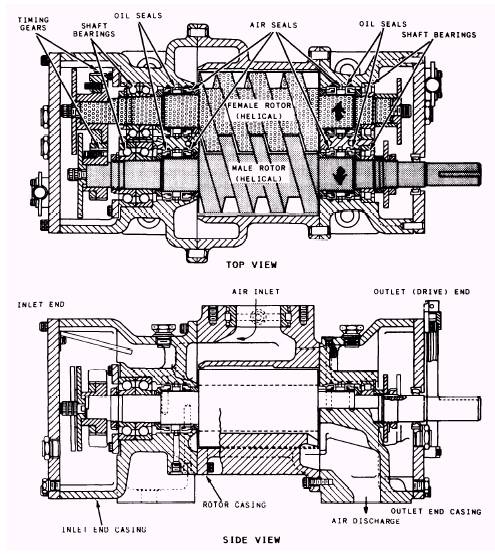
Helical
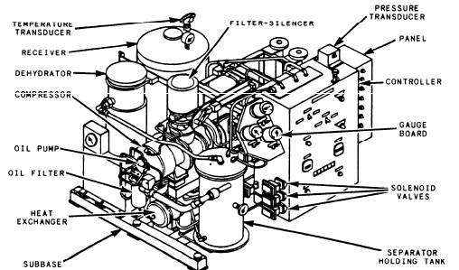
Screw Compressor A relatively new design of oil-free air compressor is being installed aboard some of our newer ships, such as the FFG-7 class and CG-47 class ships. This low-pressure air compressor is a single-stage, positive-displace-ment, axial-flow, helical-screw type of compres-sor. It is often referred to as a screw-type compressor. (Refer to figs. 14-20 and 14-21.) Compression is caused by the meshing of two helical rotors (male and female) located on parallel shafts and enclosed in a casing. Air inlet and outlet ports are located on opposite sides of the casing. Atmospheric air is drawn into the compressor through the filter-silencer. The air passes through the air cylinder-operated unloader (butterfly) valve and into the inlet part of the compressor when the valve is in the open (load) position. Fresh water is injected into the airstream as it passes through the inlet port of the compressor casing. The injected fresh water serves two purposes: (1) it reduces the air discharge temperature caused by compression, and (2) it seals the running clearances to minimize air leakage. Most of the injected water is entrained into the airstream as it moves through the compressor. The compression cycle starts as the rotors unmesh at the inlet port. As rotation continues, air is drawn into the cavity between the male rotor lobes and into the grooves of the female rotor. The air is trapped in these grooves, or pockets, and follows the rotative direction of each rotor. As soon as the inlet port is closed, the compression cycle begins as the air is directed to the opposite (discharge) end of the compressor. The rotors mesh, and the normal free volume is
Figure 14-20.-Low pressure, oil-free rotary helical screw compressor.
Figure 14-21.-Helical screw compressor. reduced. The reduction in volume (compression) continues with a resulting increase in pressure, until the closing pocket reaches the discharge port. The entrained water is removed from the discharged air by a combined separator and water holding tank. The water in the tank passes through a seawater-cooled heat exchanger. The cooled water then recirculates to the compressor for reinjection. During rotation and throughout the meshing cycle, the timing gears maintain the correct clearances between the rotors. Since there is no contact between the rotor lobes and grooves, between the rotor lobes and casing, or between the rotor faces and end walls, no internal oil lubrication is required. This design allows the compressor to discharge oil-free air. For gear and bearing lubrication, lubricating oil from a force-feed system is supplied to each end of the compressor. Mechanical seals serve to keep the oil isolated from the compression chamber. |
 |
|
|
||