| Tweet |

Custom Search
|
|
 
|
||
|
BOILER
CONTROLS Methods of operating auxiliary boilers may be manual, semiautomatic, or automatic. Any controls installed on auxiliary boilers will depend on the method of operation. The feedwater controls that are used may be classified as the (1) thermomechanical, (2) float, or (3) electrode type. We will briefly explain each type. Thermomechanical feedwater regulators are used on water-tube, natural-circulation boilers. The control element depends on the water level in the boiler steam drum. Thus, a certain water level in the drum corresponds to a certain opening of the feedwater control valve. The float type of feedwater regulating and low-water cutoff controls are used on water-tube and fire-tube boilers designed for semiautomatic or automatic operation. These controls consist of a float chamber, a float, and a switch. The float chamber is connected to the boiler drum so that the water level in the chamber is always the same as the water level in the drum. The float is interlinked with a switch which is wired into the feed pump control circuit. The switch contacts are open when the water level in the drum and float chamber is normal. A drop in the water level closes the switch contacts. This reaction starts the feed pump. When the water level is restored to a predetermined high position, the switch breaks
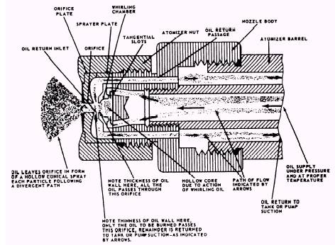
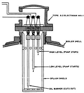
Figure 18-15.-Variable-capacity, pressure-atomizing burner, showing oil flow. the contact and stops the feed pump. The low-water cutoff feature consists of an additional switch. This switch is mounted in the same case as the pump switch but is wired into the burner circuit. If the water level drops below a permissible minimum, the low-water cutoff switch breaks the burner circuit and stops the burner. Electrode-type feedwater regulating and low-water cutoff controls are used on water-tube and fire-tube boilers designed for semiautomatic or automatic operation. These controls consist of an electrode assembly and a water level relay. The electrode assembly contains three electrodes of different lengths, corresponding to the high, low, and cutoff water levels in the boiler drum. A typical water level electrode assembly is illustrated in figure 18-16. The electrode assembly is installed on the top of the boiler drum so that the normal water level is at approximately the midpoint between the high-level and the low-level electrodes. The electrodes are electrically wired to the water level relay assembly. The relay contains the feedwater pump START and STOP contacts, which are wired to the feedwater pump controller, and the low-water cutoff, which is wired into the burner circuit. The feed pump is started when the water level in the boiler drops below the middle electrode. After the water level is restored and reaches the high-level electrode, the feed pump
Figure 18-16.-Water level electrode assembly. is stopped. In the event the water level is not restored and drops below the longest electrode, the cutoff contacts of the water level relay stop the burner by breaking the burner circuit. Pressure-limit switches and pressuretrols are operated by steam pressure. A typical pressure switch is shown in figure 18-17. They control burner operation within a fixed range of boiler pressures. Basically, they consist of a bellows assembly linked with a snap switch through a pressure-adjusting mechanism. The bellows assembly expands or contracts with any increase or decrease in boiler pressure and causes the snap switch to open or close its contacts. The pressure-adjusting mechanism is set so that the contacts open and close at specified values of cutout and cut-in boiler pressures. The differential between the cutout and cut-in pressures may be either adjustable or fixed. On boilers set up for automatic operation, the snap switch is wired into the burner electric circuit so that it will break the circuit and stop the burner when the cutoff pressure is reached and will make the circuit and restart
Figure 18-17.-Pressure switch for an auxiliary boiler. the burner when the boiler pressure falls below the cut-in pressure. On boilers set up for semiautomatic operation (manual ignition), the snap switch is wired into the burner circuit in such a way that it will break the circuit at the cutoff pressure and will hold it open, preventing manual restart of the burner, until pressure falls below the cut-in setting. Modulating pressuretrols are steam-operated rheostat switches used for automatic regulation of oil and air admission to the burners. These switches are similar in design to limit pressuretrols, except they are equipped with a potentiometer coil (a variable electrical resistance element). The switch is wired into the circuit of a reversing type of motor which operates the linkage of the air-oil ratio adjusting mechanism. When boiler pressure increases or decreases with variation of the boiler load, the bellows assembly of the switch expands or contracts, causing a sliding contact to move across the resistance element (potentiometer coil). The change in electrical balance of the motor circuit causes the motor to rotate. The movement of the motor, transmitted by a crank arm to the linkage between the fuel metering valve and the damper air vanes, resets the oil metering valve and the damper to positions corresponding to the firing rate required by the boiler load. |
 |
|
|
||