| Tweet |

Custom Search
|
|
 
|
||
|
MECHANICAL
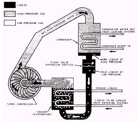
COOLING EQUIPMENT Almost all working and living spaces on newer ships are air conditioned. The cooling equipment used on these ships was carefully tested to see which types would best dehumidify and cool ship compartments. Two basic types of equipment have been found most effective and are now in general use. They are chilled water circulating systems and self-contained air conditioners. CHILLED WATER CIRCULATING SYSTEMS Two basic types of chilled water air-conditioning systems are now in use. They are a vapor compression unit and a lithium bromide absorption unit. In the vapor compression unit, the primary refrigerant cools the secondary refrigerant (chilled water) that is used to cool the spaces. This type uses the vapor compression cycle and R-11, R-12, R-22, or R-114 as the pri-mary refrigerant. The type of primary refrigerant depends on the size and type of compressor. The lithium bromide unit operates on the absorption cycle and uses water as the primary refrigerant. Lithium bromide is used as an absorbent. Lithium bromide plants are primarily used on submarines. Vapor compression plants are primarily used on surface ships. We will discuss only the vapor compression cycle in this chapter. Vapor Compression Units The vapor compression chilled water cir-culating system differs from a refrigerant circulating (direct expansion) air-conditioning system in this way: The air is conditioned by use of a secondary refrigerant (chilled water) which is circulated to the various cooling coils. Heat from the air-conditioned space is absorbed by the circulating chilled water. Heat is then removed from the water by the primary refrigerant system in the water chiller. In large tonnage vapor compression systems, the compressor is a centrifugal type that uses R-11 or R-114 as the primary refrigerant. The operating cycle of the centrifugal refrigeration plant shown in figure 17-7 is basically
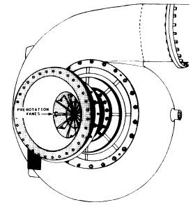
Figure 17-7.-Vapor compressor (centrifugal) unit. the same as other refrigeration plants except for the method of compression. In this type of plant, the refrigerant gas is pressurized by a centrifugal turbocompressor. Then, the gas is discharged into the condenser where it changes state from a gas to a liquid by means of cool seawater circulating through the condenser tubes. The condensed liquid refrigerant drains to the bottom of the condenser into high-pressure liquid orifice chambers. When the refrigerant level is high enough, a float-operated valve opens. (NOTE: In some R-11 units, which originally used a float valve, an orifice has been installed.) The action of these orifices allows the liquid high-pressure refrigerant to flow to the bottom of the water chiller (evaporator) at a controlled rate. Water to be chilled flows through the tubes of the water chiller. As the refrigerant from the condenser boils around and over the tubes, the water within the tubes is chilled or cooled by the vaporization (boiling) of the liquid refrigerant. The vaporized refrigerant then reenters the suction side of the compressor to start the cycle again. The load on the air-conditioning plant is determined by the temperature and flow of the returning chilled water. The compressor load is changed by either an increased or decreased demand of the chilled water. Upon demand, the load is changed by the use of adjustable prerotation vanes, which are located on the suction side of the compressor. The vanes act as dampers to increase or decrease the flow of refrigerant vapor through the inlet of the compressor. This throttling action at the compressor suction allows an increase or decrease of the capacity of the compressor without a change in the compressor speed. Figure 17-8 shows a centrifugal compressor with the inlet piping removed. Note that the prerotation vanes are in the fully open position. The vane position is normally controlled automatically through an electropneumatic control system. The control system senses and maintains the chilled water outlet temperature of the chiller at a preset value by varying the position of the vanes. In some plants, the electric motor that drives the compressor is hermetically sealed and is cooled by a flow of refrigerant through it. The compressor is lubricated by a forced feed lubrication system. This system normally consists of an auxiliary oil pump, an attached oil pump (integral with compressor), an oil cooler, and a set of oil filters. The auxiliary oil pump is used when starting and securing the plant.
Figure 17-8.-Suction end of a centrifugal compressor showing prerotation vanes. Several automatic controls are built into the centrifugal compressor control system. These devices increase the reliability of the plant by automatically shutting down the compressor if a hazardous situation develops. Some of these conditions are high condenser pressure, low compressor lube oil pressure, loss of seawater to the condenser, loss of chilled water, low refrigerant temperature, low chilled water temperature, and high compressor discharge temperature. A heater warms the oil in the sump of the compressor during plant shutdown. If the oil is not kept heated, it absorbs large amounts of refrigerant. This results in excessive oil foaming when the unit is started. The heaters in most plants are connected so that they are automatically turned on when the compressor is off and auto-matically turned off when the compressor is on. Figure 17-9 shows a centrifugal compressor air-conditioning unit. This particular plant has a 150-ton capacity and uses R-114 as the refrigerant. The gauges and controls for the plant are on the control panel. |
 |
|
|
||