| Tweet |

Custom Search
|
|
 
|
||
|
FUEL
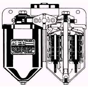
SYSTEMS In this section we will deal with diesel engine fuel systems. Fuel systems are divided into two groups: external fuel systems and fuel injection systems. EXTERNAL FUEL SYSTEMS The fuel system in a diesel-powered naval vessel must be installed, operated, and maintained with the same care and supervision as the ships engines. Inspections, maintenance, and operation of fuel tanks and fuel-handling equipment must be carried out according to the Ships 3-M Systems and the Naval Ships Technical Manual, chapters 541 and 542. The fuel is pumped from the storage tank to the service or day tank, and from there it is delivered to the fuel injection equipment on the engine. It is good practice to remove sediment and water from the fuel before it enters the service tank. This is usually done with a centrifugal purifier. The fuel is transferred from the service tank by an engine-driven pump (also called a booster, transfer, or primary pump) through a metal-edge strainer and a cartridge-type re-placeable element filter to a header at the inlet of the fuel injection equipment installed on the engine. Excess fuel (that is NOT used for combustion) is returned to the service tank. The service or day tank is usually vented to the atmosphere and mounted at a high point in the fuel system, which allows the weight of the fuel to pressurize the external system and prevent air from leaking into the system. The presence of air in the fuel will interfere with proper operation of the fuel injection equipment. The engine-driven fuel transfer pump is the positive-displacement type. Usually the fuel transfer pump is equipped with a built-in relief valve to ensure constant pressure to the injection equipment. The fuel strainer is located on the suction side of the transfer pump, and the filter is connected into the system on the discharge side of the pump. The pressure drop across these filters and strainers increases with time. For this reason, some systems have a relief valve in the line before the cartridge filter so that the bypassed fuel can be returned directly to the supply tank. The relief valve provides a more constant fuel supply pressure. The primary metal-edge fuel strainer used in Navy installations is a duplex type, which is actually two complete strainers connected by a suitable header or piping. This arrangement allows
Figure 9-4.-Primary fuel metal-edge strainer. either strainer to be completely cut out of the system for cleaning or repair while all of the fuel flows through the other strainer. Figure 9-4 shows a typical metal-edge strainer. A magnified view of a portion of the element is shown in figure 9-5. The fuel flows from the outside to the inside. In Navy-approved strainers, the spaces between the leaves, or ribbons, which act as fuel passages, are between 0.001 and 0.0025 inch. The pressure drop across these strainers must not be allowed to exceed 1.5 psi when a fuel flow is equal to the full capacity of the fuel pump. In some engines, a duplex strainer is placed between the fuel supply tank and the transfer pump and, during operation, may be working under a vacuum. The secondary, cartridge-type, fuel filter contains elements that must conform to Navy specifications. The pressure drop across clean and new elements should not be allowed to exceed 4.5 psi. The elements should be changed when the pressure drop reaches the value specified in the manufacturers instruction book. The sump of the filters and strainers should be drained as often as practicable, preferably when the fuel is flowing. |
 |
|
|
||