| Tweet |

Custom Search
|
|
 
|
||
|
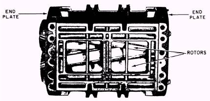
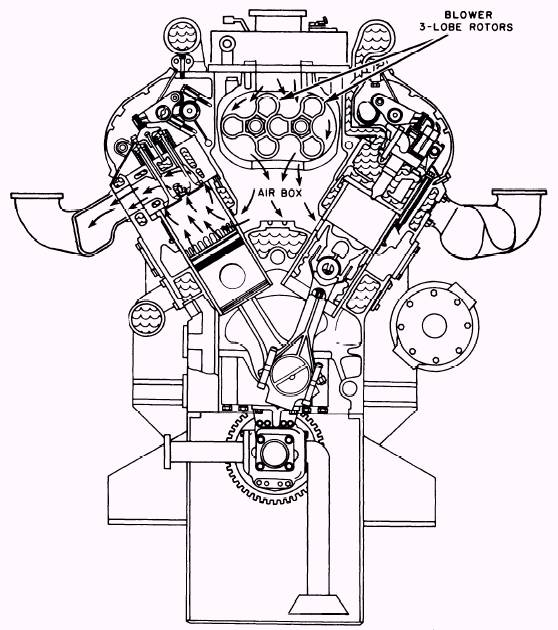
Blowers Blowers are necessary on most 2-stroke cycle engines to force scavenging air through the cylinders. In addition, a supercharged engine, either 2- or 4-stroke cycle, must have a blower to fill the cylinder with fresh air at a pressure above atmospheric pressure before the compression event starts. Basically, the primary function of an engine blower is to deliver a large volume of air at a low pressure. There are two principal types of blowers, POSITIVE DISPLACEMENT and CENTRIFU-GAL. A positive displacement blower is usually gear-driven directly by the engine, while a centrif-ugal blower is usually driven by an exhaust-gas turbine. Positive displacement blowers may be di-vided into two groups; the multiple-lobe type, commonly called the LOBE, or ROOTS, blower; and the AXIAL-FLOW, or Whitefield, blower. Blowers are introduced briefly in Fireman, NAVEDTRA 10520-F. The first example of a blower we will discuss is the roots blower. The roots blower is commonly used on many 2-stroke cycle engines. The other ex-ample we will discuss is an exhaust-driven centrif-ugal type of blower (turbocharger) that is found in many 4-stroke cycle engines and in some 2-stroke cycle engines. ROOTS BLOWER.-Designed for efficient diesel operation, the roots blower shown in figure 6-7 supplies the fresh air needed for combustion and scavenging. The air volume needed for the engine to perform scavenging is about 40 times
Figure 6-7.-Roots blower (V-71). greater than the cylinder volume. The location of the blower on the engine depends on the cylin- der arrangement. Figure 6-8 shows the location of the roots blower on a V-type engine. Figure 6-2 shows the blower location on an in-line engine. The operation of the blower is similar to that of a gear-type pump. Two hollow 3-lobe rotors revolve in opposite directions. (Refer to fig. 6-8.) When the rotors turn, air is drawn in the space between the lobes at the inlet, is trapped, and is carried around to the discharge side. The meshing lobes at the discharge side force the air out of the lobe pockets and into the air box, where the air is then available for use.
Figure 6-8.-Air intake system through a roots-type blower on a V-type engine (General Motors series 149). So that a continuously uniform supply of air can be maintained, the rotor lobes are made with a helical (spiral) shape (fig. 6-9). In the helical design, one discharge phase begins before the previous discharge phase is entirely completed, and the lobes are said to overlap. This over-lapping tends to produce a smoother discharge of air than could be realized if the rotor lobes were of a straight design. Helical timing gears located on the drive end of the rotor shafts prevent the meshing rotor lobes from touching (refer to fig. 6-9). Each rotor is supported in the doweled end plates of the blower housing by a roller bearing at the front end and by a 2-row radial and thrust ball bearing at the gear end. Lubrication of the blower bearings, timing gears, and governor drive is provided through oil passages that lead from the main oil galleries of the engine to an oil passage in each end plate of the blower. The rotor lobes require no lubrication since they are prevented from touching by the timing gears. |
 |
|
|
||