| Tweet |

Custom Search
|
|
 
|
||
|
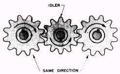
GEARS When the driving mechanism of an engine consists only of gears, the mechanism is commonly called a gear train. In a gear train, the gears must be accurately cut and heat-treated to resist wear. Helical teeth (teeth placed at an angle) are frequently used in place of spur teeth (teeth placed straight) for greater quietness and more uniform trans-mission of power. Gears and shafts are used in various arrangements to drive the vital components and accessories of the engine. The gear train for a GM 6-71 engine is shown in figure 5-1. (The arrangement shown is designed for right-hand rotation.) The gear train of a GM 71 functions as both the camshaft drive and the accessory drive. The train consists of five helical gears completely enclosed at the rear end of the engine. Note that all gears are driven by the crankshaft gear through an idler gear. An idler gear is placed between two other gears to transfer motion from one gear to the other without changing their direction. The use of a single idler gear is shown in figure 5-2. In the GM 71 shown in figure 5-1, the idler gear may be located on either the right or left side of the engine, depending upon the direction of the crankshaft rotation. (Locate the spacer, or dummy hub.)
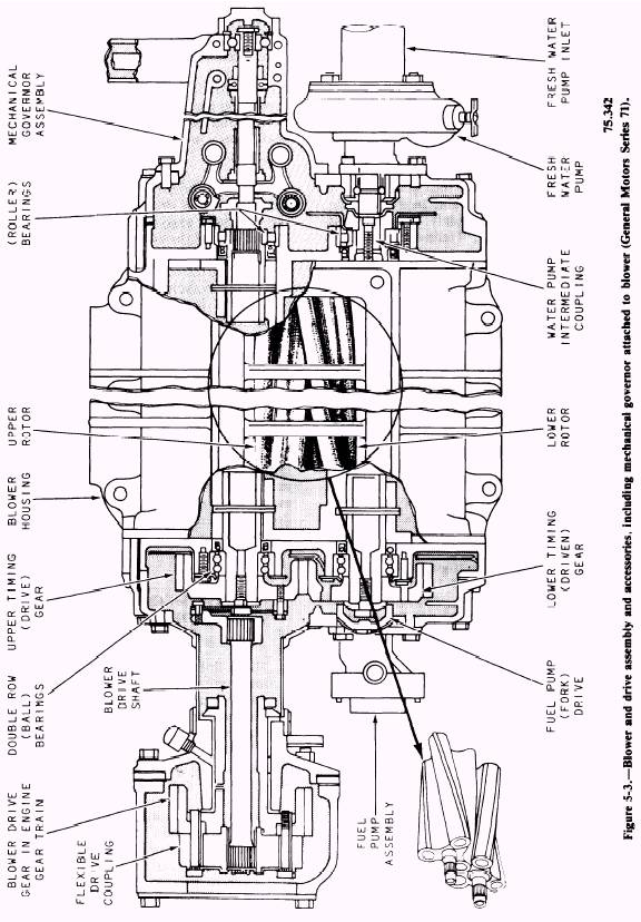
Figure 5-2.Idler gear. Since the engine operates on a 2-stroke cycle, the camshaft and balancer gears are driven at the same speed as the crankshaft gear. Either the cam-shaft gear or the balancer gear may be driven by the crankshaft gear through the idler gear; the drive arrangement depends on the model (right-or left-hand rotation). The camshaft and balance shaft gears are counterweighted for balance purposes. The accessories of the GM 71 receive power from the blower drive gear, which is driven by the camshaft gear (fig. 5-1). Located on the blower side of the engine and supported by the rear end plate, the blower drive gear transmits power to the blower, governor, water pump, and fuel pump, as shown in figure 5-3. Figure 5-3 also shows the location of the various engine accessories and the shafts, gears, and couplings that transmit the power from the blower drive gear to each of the accessories. The blower end of the governor drive shaft is serrated or splined, and it engages with corresponding serrations or splines inside the upper blower shaft. The fuel pump is bolted to the rear cover of the blower and is driven from the lower blower rotor shaft, through a device that acts as a universal joint. The water pump is mounted on the front end of the blower and is driven by the rotor shaft, through a coupling. (See fig. 5-3.)
|
 |
|
|
||