| Tweet |

Custom Search
|
|
 
|
||
|
CRANKSHAFT
TERMINOLOGY
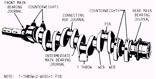
The parts of a crankshaft may be identified by various words. However, the terms in figure 4-19 are the ones that are most commonly used in the NAVSEA technical manuals for the engines used by the Navy. The MAIN JOURNALS serve as the points of support and as the center of rotation for the shaft. As bearing surfaces, the main journals and the connecting rod journals of crankshafts are surface-hardened so that a longer wearing, more durable bearing metal can be used without causing excessive wear of the shaft. As illustrated in figure 4-19, crankshafts have a main journal at each end of the shaft with an intermediate main journal between the cranks. Each CRANK (throw) of a shaft consists of three parts, two webs and a pin, as shown in figure 4-19. Crank webs are sometimes called cheeks or arms. The cranks, or throws, provide points of attach-ment for the connecting rods, which are offset from the main journals. In many crankshafts, especially in large engines, the connecting rod journals and main journals are of hollow construction. Hollow construction not only reduces weight considerably but also increases torque capability of the crankshaft and provides a passage for the flow of lubricating oil (fig. 4-20). The forces that turn the crankshaft of a diesel engine are produced and transmitted to the crankshaft in a pulsating manner. These pulsa-tions create torsional vibrations, which are capable of severly damaging an engine if they are not reduced, or dampened, by opposing forces. Many engines require an extra dampening effect to ensure satisfactory operation. It is provided by a torsional vibration damper mounted on the free end of the crankshaft. Several types of torsional dampers are currently in use. On some crankshafts, part of the web of the crankshaft extends beyond the main journal to
Figure 4-19.One-piece, 6-throw crankshaft.
Figure 4-20.An example of hollow connecting rod journal construction. form or support counterweights. These counter-weights may be integral parts of the web (fig. 4-19) or may be separate units attached to the web by studs and nuts, or setscrews (fig. 4-21). Counterweights balance the offcenter weight of the individual crank throws and thereby compensate for centrifugal force generated by each rotating crank throw. Without such balance, the crank action will create severe vibrations, particularly at the higher speeds. If such vibrations are not controlled, the shaft would become damaged. Excessive vibration may lead to complete failure of the engine. Counterweights use inertia to reduce the pulsating effect of power impulses in the same manner as the flywheel. Flywheels are described later in this chapter. |
 |
|
|
||